Bed Lever
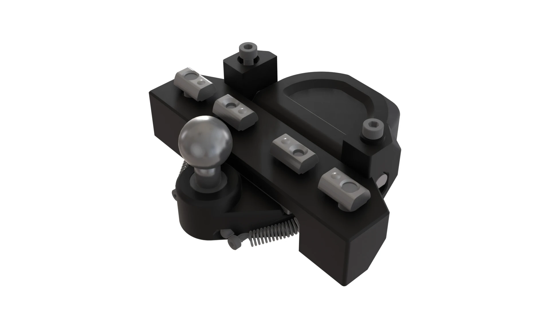
Materials
The channel magnet is STRONG, and also rather fragile. Use caution with ferrous metal nearby, especially the strike plate that goes with the lever. Also, be careful not to overtighten the magnet’s mounting screws; it will fracture.
| Hardware | Qty |
|---|---|
| Channel Magnet - 40mm | 1 |
| Bar Magnet Striker - 40mm [attached to Channel Magnet] | 1 |
| (Dual Hook Tension) Spring - 4x25mm | 2 |
| Tooling Ball | 1 |
| M5 Hex Nut | 1 |
| M5x10x1 Washer | 1 |
| M3x60 Dowel | 2 |
| M5x60 D-Shaft | 1 |
| M5x16 BHCS | 2 |
| M3x12 SHCS | 2 |
| M3x10 FHCS | 4 |
| M2x8 SHCS | 6 |
| M5 Roll-In Nut | 2 |
| M3 Roll-In Nut | 2 |
| M3 Hex Nut | 2 |
| Printed Parts | Qty |
|---|---|
| Bed Lever Frame Mount | 1 |
| Bed Lever | 1 |
Animated Assembly
WIP notes:
- The video shows the Front Z Joints being assembled before the bed lever. Feedback has suggested it is easier to attach the bed lever to the extrusion first to center it, then to move on to the Z Joints
Assembly Notes
- 3:38 Dowels are here to increase rigidity. They should not fall out once inserted, if they do, either adjust your shrinkage compensation or use a bit of glue if they’re not too loose.
- 3:51 Use some threadlocker on the M5 Hex Nut to secure the Tooling Ball.
- 3:57 Tighten by the shank only.
- 4:12 The shaft should be a really snug fit and will only go into the lever if the flat face is down.
- 4:22 Use the M2 SHCS to leverage the spring’s hook into position.
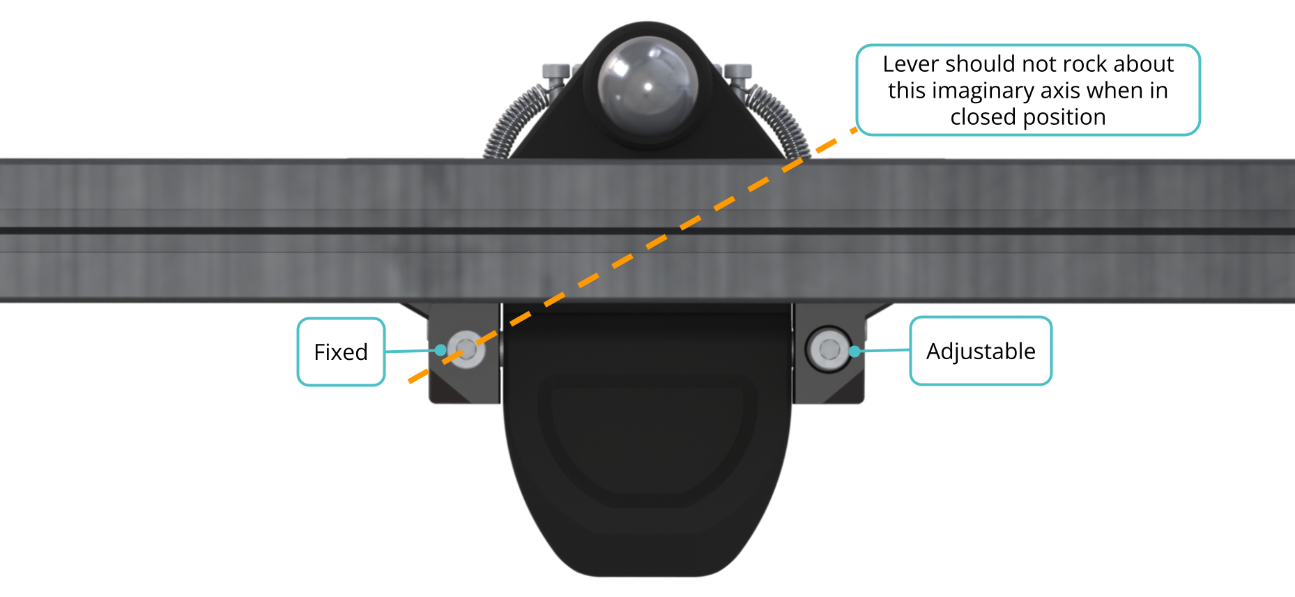
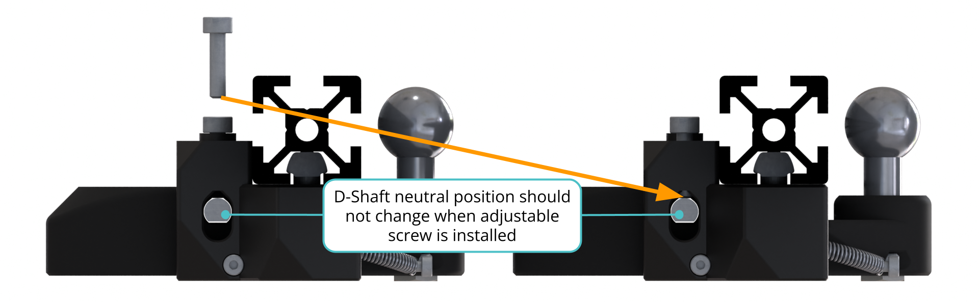
4:30 Make sure the lever is in closed position. Place a dab of glue on the fixed M3x12 SHCS and screw until the head touches the printed stud. Screw in the adjustable M3x12 SHCS until it just touches the D-Shaft. Check for any play in the bed lever by trying to rock it across an imaginary axis from the fixed M3x12 SHCS on Side A to the corner of the strike plate on Side B. If there is play when the lever is closed, make sure the adjustable M3 screw is not pushing on the D-shaft and that the magnet and strike plate are properly installed. Check that no pieces of metal or debris got stuck under the magnet. When the lever feels solid, remove the adjustable M3x12 SHCS, drop a dab of glue on its threads, and screw it back to where it was touching the D-Shaft now that you know what you’re doing.
5:21 Don’t let the lever snap closed! You could seriously injure a finger or break the magnet.
The lever is designed such that the magnet and strike plate – installed at a slight angle – create a line contact, analogous to 2 points. The fixed M3 screw provides a 3rd point contact. The lever is further constrained in Rz, X, and Y by the hinge. This means that the adjustable M3 screw on Side B is an overconstraint when the lever is closed. It is used to constrain the lever motion during the opening action that allows the bed to rotate vertically (hence Vertigo 😵💫).