Extruder Plate
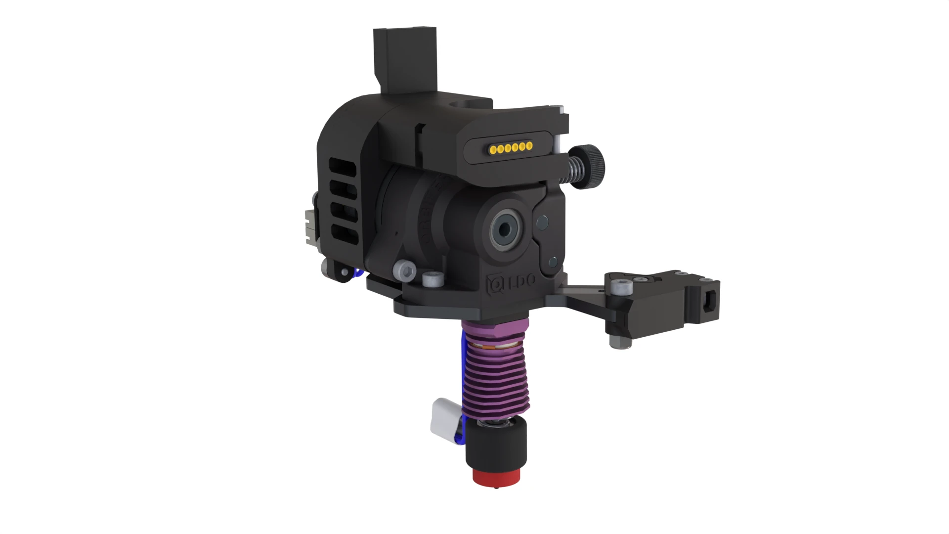
Go to the Configuring the Toolhead Board section of the Wiring Guide to set up the toolhead board before install.
Materials
| Hardware | Qty |
|---|---|
| E3D Revo PZ Probe Coldside | 1 |
| E3D Revo Heatercore - Vertigo Mk1 edition | 1 |
| E3D Revo Nozzle | 1 |
| Toolhead Plate - CNC Steel | 1 |
| PTFE Tube - 2mm ID | 1 |
| Torsion Spring | 1 |
| Razor Blade: Excel 20005 | 1 |
| LDO Orbiter Extruder | 1 |
| Magnet 1/4in Countersunk | 2 |
| Switch - D2HW | 2 |
| M3x40 SHCS | 2 |
| M3x30 SHCS | 2 |
| M3x14 SHCS | 1 |
| M3x8 SHCS | 1 |
| M3x10 FHCS | 4 |
| M2x16 SHCS | 1 |
| M2x8 SHCS | 4 |
| M2x8 FHCS | 2 |
| M3 Nyloc Nut | 3 |
| M2 Hex Nut | 2 |
| M3x5.7 Brass Insert | 4 |
| Zip Tie | 2 |
| Pogo Pin Cables |
|---|
| Z-102 |
| Z-103 |
| Z-104 |
| Heatercore Cables |
| Z-108 |
| Z-109 |
| X Endstop Cable |
| Z-100 |
| PZ Probe Controller Cable |
| Z-107 |
| Extruder Motor Cable |
| Z-101 |
| Printed Parts | Qty |
|---|---|
| Razor Lever - Bottom | 1 |
| Razor Lever - Cap | 1 |
| Razor Lever - Top | 1 |
| Toolhead Board Mount | 1 |
| Toolhead Heatbreak Riser | 1 |
| Toolhead Motor Arch | 1 |
| Toolhead Pogo Mount | 1 |
Animated Assembly
Assembly Notes
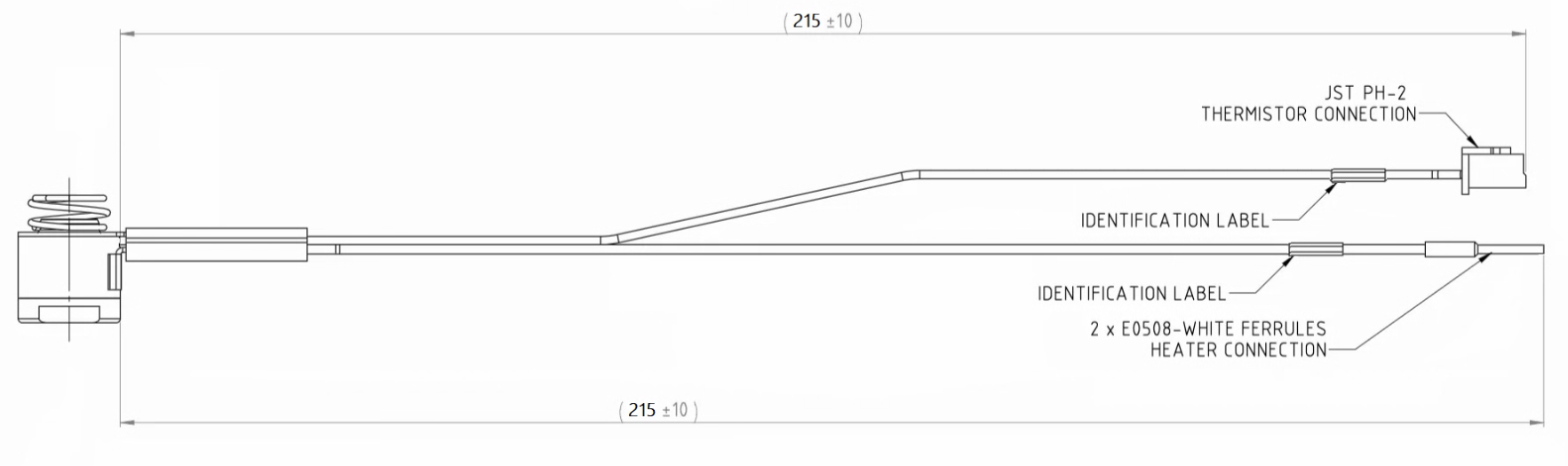
- 0:07 Unfortunately the wires that come with the standard E3D HeaterCore were not long enough to reach the toolhead board in our configuration. You must have the modified ‘Vertigo Mk1’ heater core, or modifiy the wires of your own to reach the board at your own risk. We will be releasing STLs of 3D printed tooling along with an instruction video for modifying heater core cables at a later date (WIP).
- 0:14 A tiny dab of Boron Nitride ‘anti-seize’ paste on the threads can help prevent the nozzle from unscrewing itself when printing for many continuous hours. This is also why the ‘Wall Loop Direction’ is set to ‘Clockwise’ in our default Slicer settings. We have also had success with a slightly more aggressive finger-tight approach.
- 1:48 The arrow is indicating that this hole should be visible.
- 1:54 The lower M2x8 SHCS acts like a pin to push and pull the razor; it does not screw into anything.
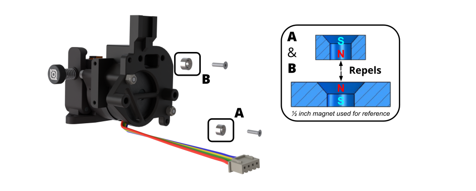
- 3:36 Magnet polarity graphic is below.
- 3:51 The flat side of the pogo connector should be on the open-ended side of the Pogo Mount, as shown in the video.
- 4:15 Make sure the zip tie nub is under the Pogo Mount. It could interfere with the cowl if it is on the side.
- 5:15 Some LDO Orbiters arrive with the filament guide protruding past the mounting surface. If it protrudes, it may interfere with the cutter. To check, place the Orbiter on a flat surface. If it rocks, the filament guide is protruding. If it sits flat, it is okay. See graphic below..
- 5:15 If the PTFE tube falls out of the LDO Orbiter, add a small bead of glue or a small piece of tape to increase its diameter. The LDO Orbiter is not designed for this low-profile filament cutting setup, so this short PTFE tube is used as a workaround.
- 6:04 See the notes in the PZ Probe Controller section of the wiring guide for info on the other cables attached to the PZ Probe.
- 6:15 If you haven’t already, go ahead and configure the toolhead board.
- 7:26 Continue to Cowl
Magnet Polarity
LDO Orbiter
- Place the LDO Orbiter mounting surface on a flat surface.
- The toolhead board mount sits slightly lower than the Orbiter, so let it hang off the edge of your flat surface.
- Check that the Orbiter does not rock on the filament guide. If it rocks, the filament guide is protruding past the Orbiter mounting surface.
- If the filament guide needs adjustment, check that it does not rub against the extruder gears. You can rotate the gear by gently pushing it with a small flathead screwdriver.
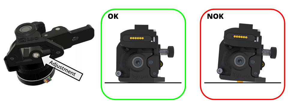
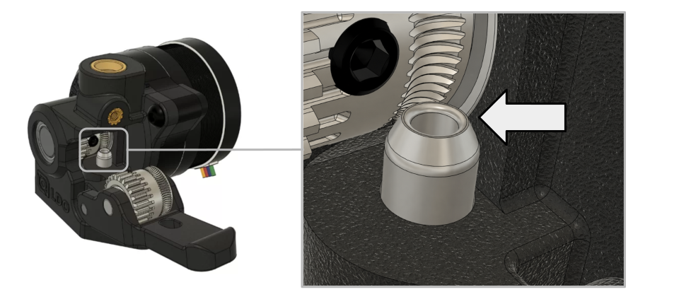
If the LDO Orbiter is adjusted too far upward, the filament guide may rub against the extruder gears during filament feeding.