Rear Z Joints
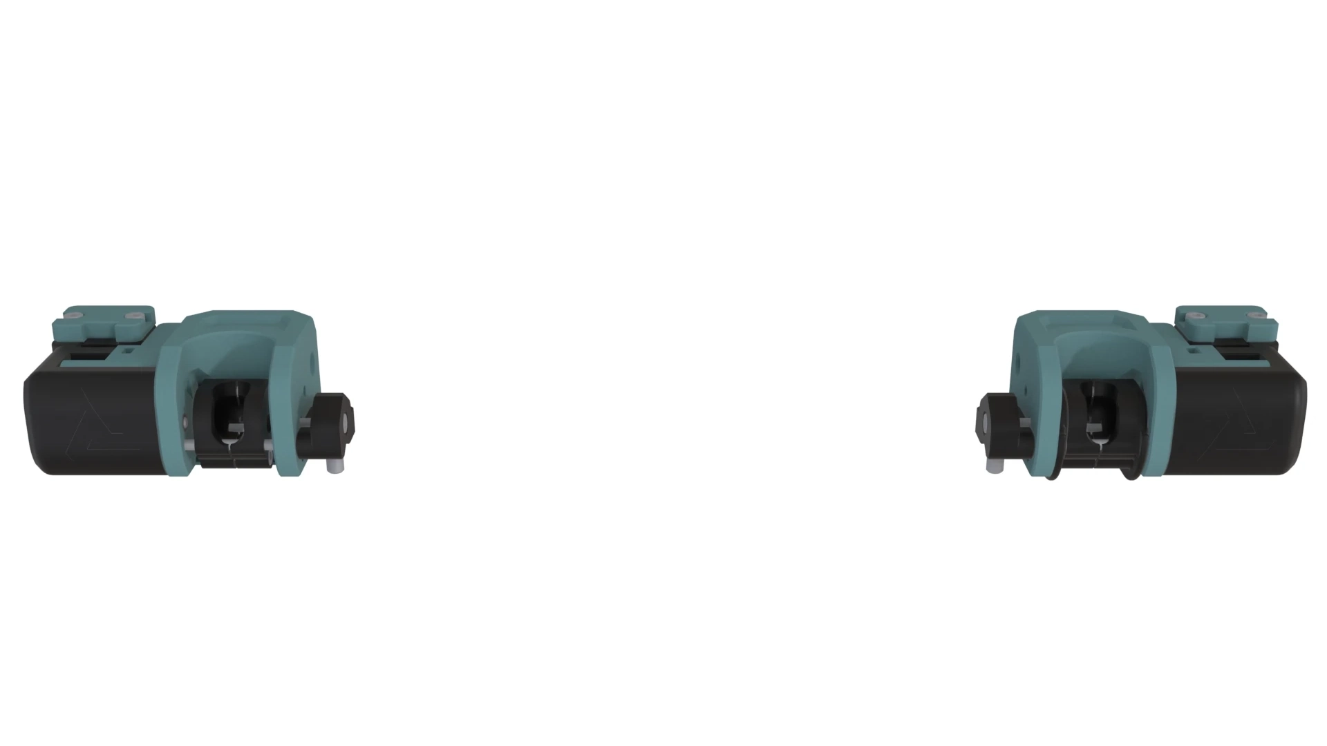
Materials
| Hardware (for each side) | Qty |
|---|---|
| M3x10Lx6W Hex Standoff (Coupling Hex Nut) | 2 |
| M3x60 Dowel | 2 |
| M5x20 BHCS | 1 |
| M3x16 SHCS | 7 |
| M3x25 SHCS | 4 |
| M3x40 SHCS | 1 |
| M3x45 SHCS | 2 |
| M3x4.3 Brass Insert (4.5) | 2 |
| M3 Hex Nut | 4 |
Animated Assembly
Assembly Notes
- 1:46 The M5x20 BHCS threads into plastic and will be used to adjust the Z Joint when the endstop is triggered. Skip any glue until calibration.
- 1:49 Dowels should be a tight press into the Dowel Caps.
- 2:03 Don’t use threadlocker or tighten these very much, they will be readjusted when the print bed is installed.
2:19 The dowels should fit into cup block tightly and not wiggle at all. If they do, adjust the holes or scaling in your slicer and reprint parts as needed. For Rear Z Joint Side A: the kinematic seatbelt should slide along the dowels, but they should not be loose, like a snug slip fit. You may apply a small amount of grease on the dowels on side A. See note below for more info.
There are two tooling balls on the rear of the bed that will fit into the kinematic “seatbelts” in these rear Z Joints. Those together with the tooling ball on the Bed Lever form a Kelvin kinematic coupling. The concept in our design is that one DOF is constrained by the Bed Lever, two on the rear Z Joint A, and three on the rear Z Joint B. This is why side B gets the seatbelt locks and side A has a bit of travel along the dowels.