Checks & Calibration
At this point, ideally you have completed:
- the Assembly Guide up to – but not including – the Enclosure section,
- the Wiring Guide, having linked back and forth from the Z Endstops, Toolhead, and Electronics Backpack sections respectively,
- the Firmware Setup, with the ability now to access your printer’s Mainsail User Interface via web browser.
Before you get printing, there are a few things left to ‘check and calibrate’. Follow this guide in order and don’t hesitate to reach out on Discord if you run into issues.
The Config Reference sections below refer to the lines in configuration files where the relevant pins, parameters, modules, and macros can be found. Unless an instruction says to ‘FIRMWARE RESTART’, simply save the config file you’re working on without a restart and continue. These files can be edited directly from Mainsail in the Machine tab in the Navigation Sidebar.
During this setup, you will move axes manually – with your hands – while the motors are disabled. Manually moving connected steppers too quickly can generate current that can damage the electronics! So go slow. 🐢
Table of Contents
- Fans
- Lights
- Endstops
- Safety Switch
- Stepper Movement
- Homing
- Axis Movement
- Nozzle Cleaner Position
- Filament Cutter Position
- Nozzle Probe
- Force Sensors
- Bed Scrape Test
- Heaters
- Resonance Compensation
- Bed Leveling (Z Tilt) Test
- Global Z Offset
- Camera Options
Fans
PSU Fan
This fan is internal to the 24V DC PSU and should be on when internal temperature is high or power loads are high. It is not specified in the config.
Electronics Backpack Fans
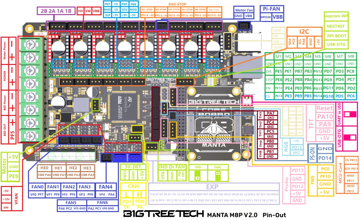
See important note here. These fans should be on when the power is on. The stock fans are not controllable, therefore they are not specified in the config. However, if you switch them out, you could control them manually via a [generic_fan] section or based on the M8P MCU temperature using a [temperature_fan] section in printer.cfg. If they are too loud or you want to control them, you can upgrade to 4-pin PC fans like these Noctua 4020 PWM Fans. Just pay attention to how the connectors are wired, and take a look at the M8P V2 Pinout.
Camera Fan
The Camera Fan should always be on. It runs on the same circuit as the logo LED, both of which are connected directly to the 24V PSU output.
Part Cooling Fan
The three part cooling fans in the Cowl operate together on the same circuit and are simply called ‘fan’ by klipper and can be controlled via the “Miscellaneous” panel in the Mainsail Dashboard.
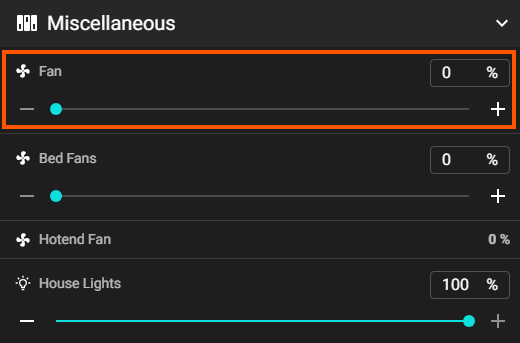
Config Reference
printer.cfg
:
[fan] # Part Cooling
pin: toolhead:gpio21
Hotend Fan
The Hotend Fan should turn on when the nozzle temperature exceeds the value defined in printer.cfg. This value is 45°C by default. We will tune the nozzle temperature control parameters later, but for now if you heat the nozzle to ~50°C, you should hear the fan spin up, feel a slight breeze on your finger behind the hotend, and see the %[fan power] value increaase in the “Miscellaneous” panel in the Mainsail Dashboard.
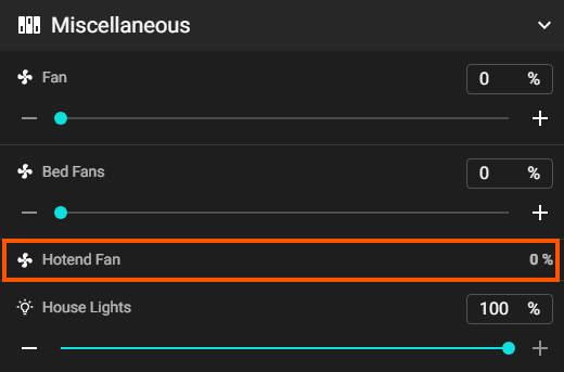
Config Reference
printer.cfg
:
[heater_fan hotend_fan]
pin: toolhead:gpio13
heater: extruder
heater_temp: 45.0
Bed Fans
The fans under the bed can help heat soak the build chamber when printing materials that like that envoronment. They also help cool the bed which helps release parts before scraping. The four fans operate together on the same circuit and are called ‘bed fans’ in the config and can be controlled via the “Miscellaneous” panel in the Mainsail Dashboard.
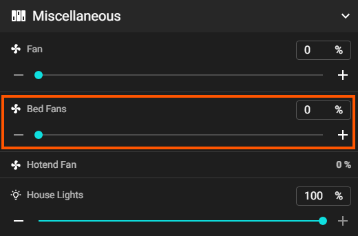
Config Reference
printer.cfg
:
[fan_generic bed_fans]
pin: PF7
Lights
VERTIGO LED
This LED at the top of the front of the printer is connected directly to the 24V PSU output, so it’s not specified in the config file.
Nozzle and Cowl Cap Logo LED
These are on the same circuit and get power from the 5V RGB output on the toolhead board, however they are wired to +5V and GND so they are not controllable or specified in the config. There was no more room to add pins to the Cowl pogo pin connector, so it would be difficult to change them to RGB.
Enclosure Lights
These are called ‘House Lights’ in the config and controllable via the “Miscellaneous” panel in the Mainsail Dashboard.
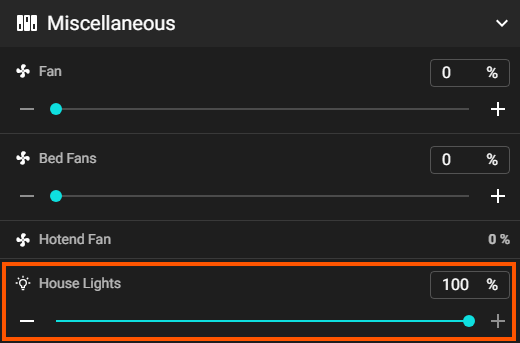
Config Reference
printer.cfg
:
[led house_lights]
white_pin: PA4
initial_WHITE: 1.0
Endstops
Trigger Check
- First make sure all motors are disabled, by power cycling or sending
M84in the Console in Mainsail. - With your hands, move the Gantry Bar to the center of the Y axis and the Toolhead to the center of the X axis.
- With the Bed Lever engaged, lift all four Z Joints several centimeters off the bottom of their travel. Make sure you can access and depress the switch on the X, Y, and four Z Endstops.
- Refresh the endstop states in Mainsail > Machine Tab > Endstops Panel > Refresh Button.
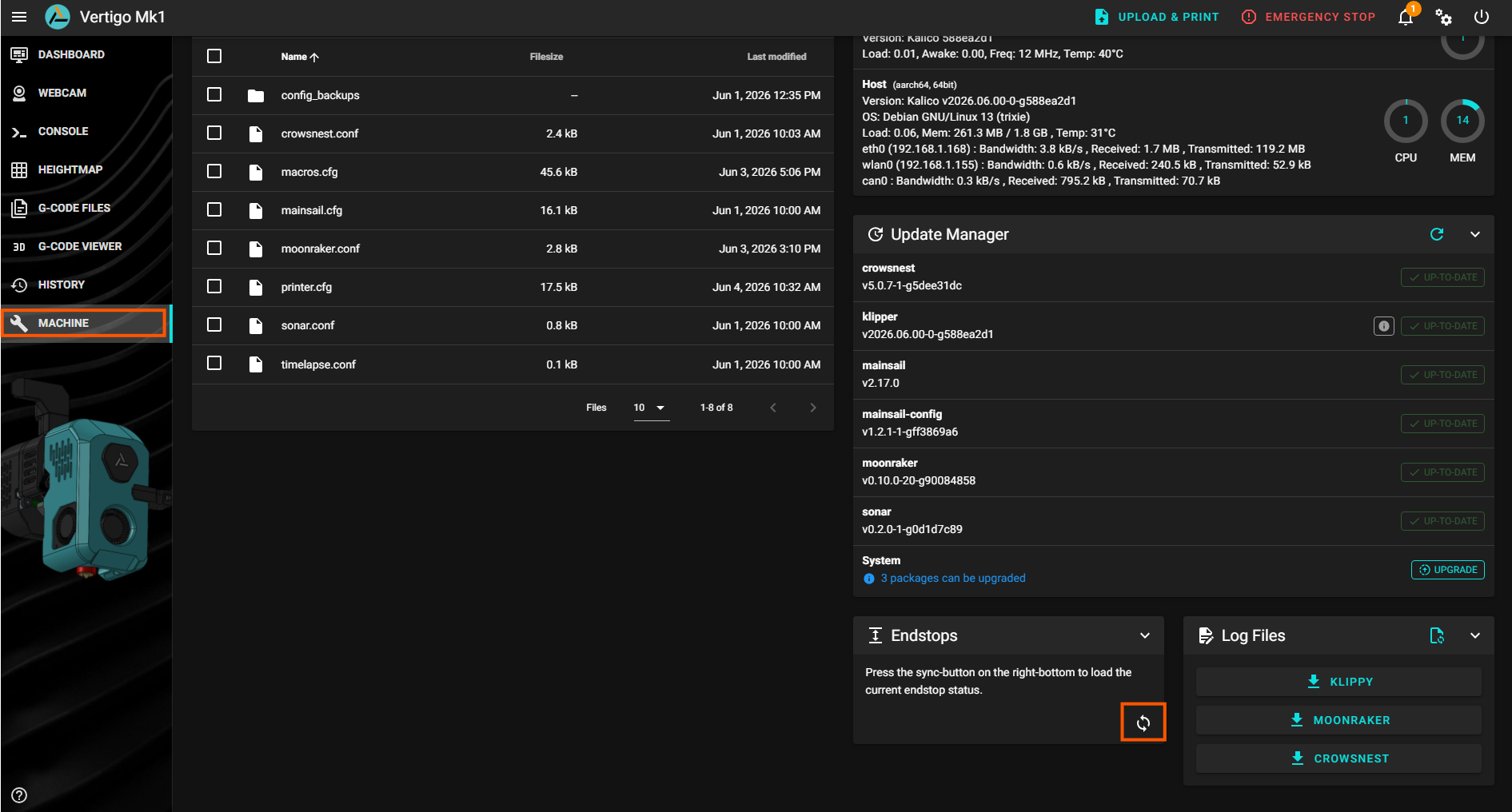
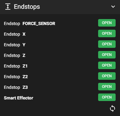
- The states should all be OPEN in the Endstops Panel.
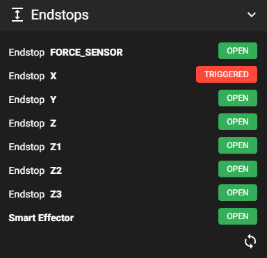
- One-by-one, hold each endstop switch down while clicking the Refresh button to verify that each switch triggers and corresponds to the proper label in the Endstops panel.
Z Endstop Location - Top View
            Rear
       z2 -------- z3
        |          |
 Side A |          | Side B
        |          |
        z -------- z1
            Front
X/Y Endstop Calibration
The X and Y endstops for the gantry have no adjustment mechanism, so you must check that both trigger as expected, first by moving the toolhead to the right up against the X endstop, then by sliding the gantry bar back until XY Joint A triggers the Y Endstop. Use the Endstops Panel in Mainsail to verify.
Config Reference
printer.cfg
:
[stepper_x]
:
endstop_pin: ^toolhead:LIMIT_X

[stepper_y]
:
endstop_pin: ^!PC15
Z Endstop Calibration
Each Z Joint has its own M5 BHCS adjustment screw. All Z Joints need to be “as close as can reliably trigger” to the bottom of the frame. A good way to do this is to:
- Make sure the bed is roughly horizontal and that the bed wheels are resting on the ramp platform.
- Unscrew the adjustment screws so that they don’t trigger the switches when the Z Joints are at the bottom of travel (leaving ~1-5mm showing on the bottom).
- Carefully push down the front Z Joint Bar so that the Bed Lever disengages and the Front Z Joints are touching the bottom of the frame.
- Push down the Rear Z Joints so that they are touching the bottom of the frame. The front of the bed shouldd tilt up slightly.
- Turn each adjustment screw until the corresponding endstop is TRIGGERED in the Endstops Panel. You can use the LED on the PCB as a guide. Give each screw an additional full turn, which equates to 0.8mm of depth. Assuming a worst case limit switch tolerance of +/- 0.1mm , this should give a gap of ~0.7-0.8mm between each Z Joint and the frame when the Endstops are triggered. These endstops are not used for levelling the bed. They are used to prepare the bed to be levelled by the probe and to be scraped after a print.
Config Reference
printer.cfg
:
[stepper_z]
:
endstop_pin: !PF4

[stepper_z1]
:
endstop_pin:!PF3

[stepper_z2]
:
endstop_pin: !PF2

[stepper_z3]
:
endstop_pin: !PF1
Safety Switch
Most printers have the ability to plow the nozzle through the build plate and cause damage if things aren’t calibrated for functioning properly. Because of the negative Z travel required for scraping the bed on the Vertigo, we have a few additional safety mechanisms. The Safety Switch prevents crashes at the top of the Front Z Axes, particularly in the event that the nozzle probe does not trigger or the front steppers are not disabled when scraping the bed. This switch will put klipper into an ‘Emergency Shutdown’ state, from which a firmware restart is required.
- Hold the Bed Lever down and manually move the Front Z Joint Bar up until the tooling ball is above the bed contact plate.
- Carefully let the Bed Lever close without snapping shut.
- Set the Safety Switch adjustment screw on Front Z Joint B so that it protrudes ~0-1mm.
- Slowly raise the Front Z Joint Bar up until the carriages – particularly on side B – are ~1-2mm below the bottom of the horizontal gantry frame extrusions.
- Turn the Safety Switch adjustment screw until the switch triggers and the system shuts down.
- Click ‘Firmware Restart’ in the power menu at the top right of the Mainsail Dashboard.
- Disengage the Bed Lever and slowly lower the Front Z Joint Bar until the tooling ball is below the bed contact plate and carefully let the Bed Lever close without snapping shut. The Bed Lever should be resting on the Bed Lever Striker, with the tooling ball below the bed contact plate. Omitting this step can break your printer!
Config Reference
printer.cfg
:
[gcode_button bed_safety_button]
pin: ^PC4

press_gcode:
  {action_emergency_stop("Impending Doom Averted!")}
Stepper Movement
We’ll use Klipper’s STEPPER_BUZZ command to safely test whether the specified motor moves in the expected direction. This command will enable the stepper, rotate it both directions a small amount 10 times, then disable the stepper. If the stepper does not move in the expected manner, you must check the wiring and pinning of the connectors of the affected stepper.
Stepper Locations - Top View
            Rear
        x          y
        |          |
       z2 -------- z3
        |          |
 Side A |          | Side B
        |          |
        z -------- z1
            Front
Z Stepper Test
The Z steppers will be tested in numerical order, front then rear. All Z Joints should move downward first.
- With your hands, raise the Front Z Joint Bar so that the Bed Lever is just above the Bed Lever Striker. It should stay there without without drooping, but you can also hold it up if you need to. The tooling ball must still be below the bed contact plate.
- In the config, stepper_z corresponds to the front stepper on side A. This is the one we will test first. In Mainsail > Dashboard Tab > Console Panel, type (or paste) the command:
STEPPER_BUZZ STEPPER=stepper_z. - Repeat the test for stepper_z1:
STEPPER_BUZZ STEPPER=stepper_z1. - Manually raise Rear Z Joint A and run the test:
STEPPER_BUZZ STEPPER=stepper_z2. - Manually raise Rear Z Joint B and run the test:
STEPPER_BUZZ STEPPER=stepper_z3.
Config Reference
printer.cfg
:
## Z0 Stepper - Front Left
[stepper_z]
dir_pin: PE5
step_pin: PE6
enable_pin: !PC14                        # active-low EN
rotation_distance: 40
gear_ratio: 80:16
microsteps: 16
endstop_pin: !PF4
full_steps_per_rotation: 200
position_endstop: 250
position_max: 250
position_min: -160
homing_speed: 15
second_homing_speed: 3
homing_retract_dist: 0
homing_positive_dir: True

[tmc2209 stepper_z]
uart_pin: PC13
interpolate: True
run_current: 1.3
sense_resistor: 0.110
stealthchop_threshold: 0
:
[stepper_z1]
:
[tmc2209 stepper_z1]
:
X/Y Stepper Test
- With your hands, move the Gantry Bar to the center of the Y axis and the Toolhead to the center of the X axis.
- In the config, stepper_x corresponds to the stepper on side A. This is the one we will test first. In Mainsail > Dashboard Tab > Console Panel, type (or paste) the command:
STEPPER_BUZZ STEPPER=stepper_x. The lower belt which is driven by stepper_x should first move toward the front of the printer. - Repeat the test for stepper_y:
STEPPER_BUZZ STEPPER=stepper_y. The upper belt on side B, driven by stepper_y should first move toward the rear of the printer.
Config Reference
printer.cfg
:
## X Stepper on Motor5 (A Motor)
[stepper_x]
dir_pin: PD7
step_pin: PG9
enable_pin: !PG11
microsteps: 32
rotation_distance: 40
full_steps_per_rotation: 200
endstop_pin: ^toolhead:LIMIT_X
position_min: 0
position_endstop: 255
position_max: 255
homing_speed: 60
homing_accel: 500
homing_retract_dist: 5
homing_positive_dir: True

[tmc5160 stepper_x]
cs_pin: PG10
spi_software_mosi_pin: PG6
spi_software_miso_pin: PG7
spi_software_sclk_pin: PG8
sense_resistor: 0.075
run_current: 2.2                         # abs max ~2.8A (stepper-limited)

## Y Stepper on Motor6 (B Motor)
[stepper_y]
dir_pin: PD3
step_pin: PD4
enable_pin: !PD6
microsteps: 32
rotation_distance: 40
endstop_pin: ^!PC15
full_steps_per_rotation: 200
position_min: 0
position_endstop: 255
position_max: 255
homing_speed: 60
homing_accel: 500
homing_retract_dist: 5
homing_positive_dir: True

[tmc5160 stepper_y]
cs_pin: PD5
spi_software_mosi_pin: PG6
spi_software_miso_pin: PG7
spi_software_sclk_pin: PG8
sense_resistor: 0.075
run_current: 2.2
Extruder Stepper Test
This test is just to make sure the stepper on the Orbiter V2 Extruder is moving in the correct direction at roughly the correct speed. We will calibrate filament extrusion later.
- Remove the Cowl.
- Place a piece of non-transparent tape on the visible end of the extruder stepper shaft.
- In the Console, run
STEPPER_BUZZ STEPPER=extruder. The tape should indicate that the stepper first rotate clockwise ~10° or a little less than 2 minute marks on an analog clock. Don’t get scientific about this it’s just a sanity check. - Remove the tape. Resist the urge to stick it on your cat.
Config Reference
printer.cfg
:
[extruder]
## Extruder movement
step_pin: toolhead:EXT_STEP
dir_pin: toolhead:EXT_DIR
enable_pin: !toolhead:EXT_EN
rotation_distance: 4.69                  # per Orbiter V2.0 Spec
microsteps: 32
full_steps_per_rotation: 200             # 1.8deg motor
:
[tmc2209 extruder]
uart_pin: toolhead:gpio15
interpolate: False
run_current: 0.85
sense_resistor: 0.110
stealthchop_threshold: 0
Homing
The the mechanics of the Vertigo Mk1 require a specific homing order: Z -> Y -> X, as well as some config parameters that prepare the bed for print-related actions, like bed leveling and mesh probing.
Z Axis Homing
To prepare for the first Z homing, each Z Joint must be lifted off its endstop so that the endstop is OPEN in the Endstops Panel in Mainsail.
- Lift Z Joint A off its endstop and run
SET_STEPPER_ENABLE STEPPER=stepper_zin the Console Panel. It’s ok if the Bed Lever is at an angle as long as the tooling ball is below the bed contact plate. Repeat for all other Z Joints. - Be prepared to turn the power off or click ‘Emergency Stop’ at the top of the Mainsail Dashboard if the Z axes move in the wrong direction (up towards the toolhead).
- Click the ‘DEBUG HOME Z’ button in the Calibration Panel in the Mainsail Dashboard.

DEBUG HOME Z is used because, as we will see and calibrate later, a standard G28 Z command will home to the endstops then raise the Front and Rear Z Joints so that the Bed Lever engages and couples to the bed contact plate.
- Verify that the Z Joints are all at the bottom of their travel and that the endstops are triggered.
X/Y Axis Homing
For the Vertigo, Y is always homed before X (because the filament cutter dowel extends a bit into the X travel of the toolhead).
- Position the Gantry Bar and Toolhead such that both endstops are OPEN in the Endstops Panel in Mainsail.
- Be prepared to turn the power off or click ‘Emergency Stop’ at the top of the Mainsail Dashboard if the Z axes move in the wrong direction (up towards the toolhead).
- Click the ‘Home Y’ button in the Toolhead Panel in the Mainsail Dashboard.
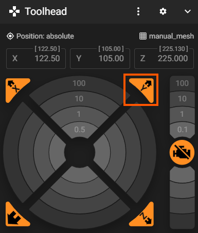
- Click the ‘Home X’ button in the Toolhead Panel in the Mainsail Dashboard.
Ready Bed Position
For any operations other than clearing the bed, it is necessary to first lift the Front Z Joint Bar so that the Bed Lever is engaged. The design allows the Bed Lever to engage with the tooling ball just below the bed contact plate to avoid a loud snap and potential denting of either the ball or plate. This behavior will be examined during this calibration. Ideally the default values here are good, but it’s good to check and understand what’s going on.
- If following the guide in order, the Z Joints should all be at the bottom of travel. If not, click ‘DEBUG HOME Z’. Double check that all Z Joints are down on the endstops.
- In the Console, run
FORCE_MOVE_Z_FRONT DISTANCE=1to raise the Front Z Joint Bar up by 1mm. You will see a readout that displays the total distance moved:front pair now +[value] mm from nominal(so far). - Keep moving the Front Z Joint Bar up until the Bed Lever engages and you can see a small gap between the Bed Lever and its striker. You can use values other than 1mm to get there and dial it in.
- Use the value in the readout
front pair now +[value] mm from nominalfor the parameterfront_engage_distance:in printer.cfg. - In the Console, run
FORCE_MOVE_Z_REAR DISTANCE=1to move the Rear Z Joints up until the tooling ball is touching the bed contact plate. The bed should be tilted slightly forward; meaning the rear of the bed is slightly higher than the front of the bed, and the Bed Wheels are not be bearing weight.The bed must be tilted slightly forward because Z_TILT_ADJUST probes the front of the bed first, then the rear of the bed. If it is tilted the other way, it’s possible that the Safety Switch will trigger during the leveling process.
- Use the value in the readout
rear pair now +[value] mm from nominalfor the parameterrear_couple_distance:in printer.cfg. - Save printer.cfg and ‘FIRMWARE RESTART’ to apply changes.
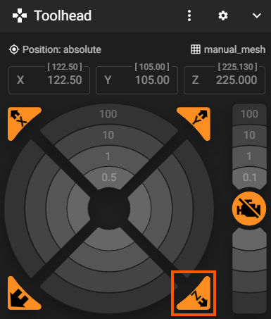
- When the interface is available again, click the normal ‘Home Z’ button in the Toolhead Panel. After homing to the endstops, the front and rear Z axes should move independently to couple the bed to the Front Z Joints.
Config Reference
printer.cfg
:
[vertigo_z_homing]
front_steppers: stepper_z, stepper_z1
rear_steppers: stepper_z2, stepper_z3
front_engage_distance: 25                # mm to raise the FRONT pair to engage the lever
rear_couple_distance: 13                 # mm to raise the REAR pair to couple the bed
lift_speed: 25                           # mm/s for the isolated front/rear moves (raises + jogs)
lift_accel: 100                          # mm/s^2 for the isolated front/rear moves
max_print_z: 230                         # optional explicit kinematic Z after print-home
Homing Sequence
If you’ve gotten this far, awesome! We’re getting closer to our first print. You should now not need to be so concerned with the power switch or ‘Emergency Stop’ button.
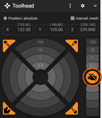
- Click the ‘Disable Motors’ button in the Toolhead Panel in Mainsail.
- Repeat step 1 of the Z Axis Homing section above to position all Z Joints above their endstops.
- Repeat Step 1 of the X/Y Homing section above to open those endstops.
- Now, clicking the ‘Home All’ or the ‘Home X’ button should home all axes in the proper sequence: Z -> Y -> X. Feel free to try both. Once the axes are homed, they know where they are and will then re-home independently.
Config Reference
macros.cfg
:
[homing_override]
Axis Movement
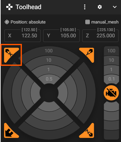
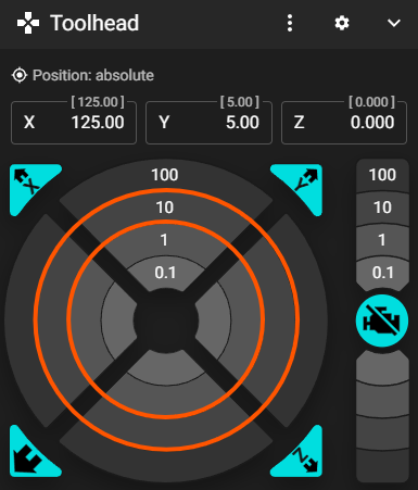
Now that the printer is homed, we’ll do a quick manual ‘jog’ to confirm the Toolhead moves nominally in X and Y and the bed moves nominally in Z – all from the Toolhead Panel in the Mainsail Dashboard. Movement consists of concentric rings of step-size buttons (e.g. 100, 10, 1, 0.1 mm). For the toolhead (X/Y Axes), the rings are divided into 4 sections with N, E, S, W corresponding to +Y, +X, -Y, -X respectively. For the bed (Z Axis), the rings above the ‘Disable Motors’ button move the bed in the ‘negative direction’ up towards the nozzle – counterintuitive perhaps, but this is from the perspective of the nozzle. Each click moves the selected axis by the chosen step size – start small. Everything must be homed first; if an axis isn’t homed, Mainsail will refuse the move.
Toolhead (X/Y) Jog Test
The Toolhead moves in X and Y. After homing, the Toolhead sits at the rear-right corner (the X and Y maximums), so we’ll jog away from there, back toward the center.
- Confirm all axes are homed from the previous section.
- At the bottom of the Toolhead Panel, reduce Speed Factor to 50%.
- In the Toolhead Panel, click the ‘-10mm X’ ring section. The Toolhead should move toward side A (left), away from the endstop. Click ‘+10mm X’ to send it back toward side B (right).
- Repeat for Y.
Be aware of the Filament Cutter when jogging. It’s possible to bump the dowel that extends into the toolhead movement area.
- Try the other step sizes and jog each axis a little to confirm the moves feel smooth, with no grinding or skipped steps.
Bed (Z) Jog Test
Before jogging Z, the Bed Lever must be engaged and the bed coupled to the contact plate. A standard ‘Home Z’ leaves the printer in exactly this state, so as long as you homed normally (not ‘DEBUG HOME Z’), you’re ready.
- If the bed isn’t already coupled, click ‘Home Z’ in the Toolhead Panel.
Whenever manually jogging the Z Axis with the Toolhead Panel, it is imperative to ensure the Bed Lever is engaged. Error checking in the
vertigo_z_homingmodule should prevent jog moves from a ‘decoupled’ state. But you know… stuff happens. If the bed contact plate is ever above the tooling ball on the Bed Lever, do the following:- Disable Motors.
- Position the Front Z Joint Bar high enough above the bed contact plate to allow the Bed Lever to open.
- Open the Bed Lever.
- Move the bed or Z Joint Front Bar so that the tooling ball is below the bed contact plate.
- Run a standard ‘Home Z’ command (G28 Z or ‘Home Z’ Button in Toolhead Panel). Z Axis jogging should now be ‘unlocked’.
- Click the +1 mm button (above ‘Disable Motors’). The bed should rise ~1 mm toward the nozzle.
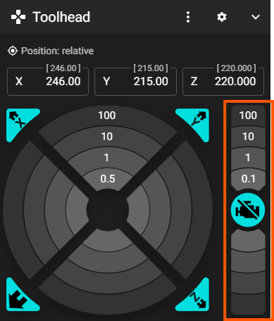
- Click the -1 mm button (below ‘Disable Motors’). The bed should lower ~1 mm away from the nozzle.
- Move the bed up and down a few millimeters to confirm smooth, quiet travel.
Do not jog below where the Bed Lever touches the striker on the frame. It may not reset properly.
The ‘negative’ Z travel allowed for scraping means that it’s possible to jog the bed up past the nozzle and into the gantry. For this test, do not move the bed within 20mm of the nozzle.
Config Reference
printer.cfg
:
[printer]
kinematics: corexy
max_velocity: 1500                       # mm/s
max_accel: 40000                         # mm/s^2
max_z_velocity: 30                       # mm/s
max_z_accel: 100                         # mm/s^2
The per-axis jog limits – how far the toolhead and bed are allowed to travel – come from the position_min / position_max values in each [stepper_*] section shown in the Stepper Movement and Endstop Calibration sections above.
Nozzle Cleaner Position
It’s important to keep a clean nozzle for bed leveling, clean first layers, and pause/resume functionality.
- Use the Toolhead Panel to jog X and Y until the nozzle is centered on the silicone nozzle plug (a repurposed Revo Nozzle Sock).
- Adjust the vertical position of the Nozzle Cleaner so that the nozzle presses into the plug.
- Jog the X axis -10mm and check that the tip of the nozzle is not below the base of the silicone brush teeth. Readjust the Nozzle Cleaner if necessary.
- Jog the X axis +10mm, back to the plug.
- Enter the X and Y positions from the Toolhead Panel into
variable_plug_pos_x:andvariable_plug_pos_y:in config_vriables.cfg. - Save config_variables.cfg.
Config Reference
config_variables.cfg
:
[gcode_macro _macro_variables]
:
# ---- Purge / wipe / plug settings ----
variable_plug_pos_x: 18
variable_plug_pos_y: -29
variable_wipe_dist: 15
variable_wipe_speed: 50                          # mm/s -> mm/min after conversion
variable_wipe_plug_dx: 12.1                      # distance between plug pos and wipe/brush center
Filament Cutter Position
The filament cutter is designed to be integrated with an automatic filament swapping system (MMU/AFC/AMS, etc.). Without one of these systems, it can still help prevent clogs by allowing you to remove filament cold, so that hot, melted filament only moves in one direction. The Vertigo uses a dowel-slot method to cut filament because the razor will not get stuck like mechanisms that rely on a spring to return the razor lever. (This has been observed in Bambu printers for example.)
- Ensure the Toolhead is homed.
- Use the Toolhead Panel to jog Y such that the Toolhead is clearly to the rear of the Filament Cutter dowel on the right side (side B) of the printer.
- Jog X and Y until the slot in the cutter arm is horizontally aligned and ~2mm from the end of the Filament Cutter dowel.
- Adjust the vertical position of the Nozzle Cleaner so that the dowel is aligned with the vertical center of the cutter arm slot.
- Enter the X and Y positions from the Toolhead Panel into
variable_cut_pos_x:andvariable_cut_pos_y:in config_variables.cfg. - Test the default
variable_cut_attach_y_dist:paramter in the Config Reference below by jogging in the negative Y direction by this amount to engage filament cutter dowel. The end of the dowel should be protruding protruding ~1-2mm out the back of the cutter arm. Editvariable_cut_attach_y_dist:as necessary and jog the Toolhead in +Y to disengage the Filament Cutter. - Save config_variables.cfg and ‘FIRMWARE RESTART’ to apply changes.
- When the interface is available again, click ‘Home All’ and test by running
CUT_FILAMENTin the Console.
Config Reference
config_variables.cfg
:
[gcode_macro _macro_variables]
:
# ---- Filament cutter settings ----
variable_cut_pos_x: 249.5
variable_cut_pos_y: 18
variable_cut_attach_y_dist: 20
variable_cut_dx: 22
variable_cut_dy: 23
Nozzle Probe
The Hitchcock Toolhead uses E3D’s high accuracy nozzle probe to level the bed and provide an absolute reference for the printers Z origin.
Here is the E3D PZ Probe Documentation. Scrolling down to the presets section is particularly helpful, but there is a lot of information there to help with sensitivity tuning.
- With everything homed, we’ll go to the first probe point specified in
[z_tilt]to test. RunG90thenG1 X125 Y5 F6000in the Console. - Remove the Cowl so you can easily access the nozzle and PZ Probe Controller.
- Press the preset button on the PZ Probe Controller on the side of the Toolhead until you are in Preset 4. The LEDs on the controller board will change as you cycle through presets. Use the images below for reference.
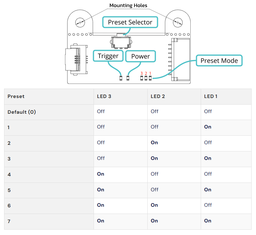
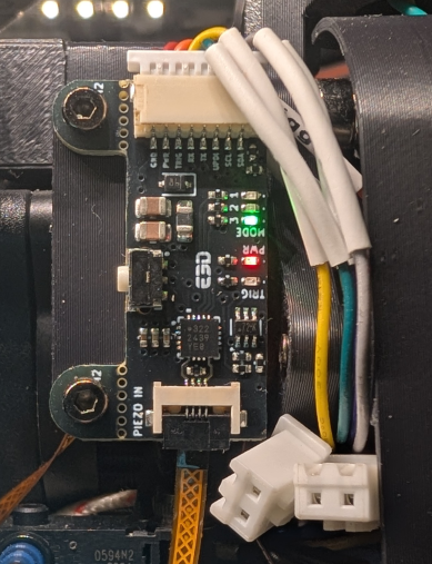
- Test the probe by tapping the nozzle from underneath with a hex key or the back of your fingernail. The trigger LED should light up when tapped.
- First we’ll do a trial run, then we’ll do the real thing. Hold something hard and relatively wide and flat under the nozzle i.e. a coaster, phone, etc. We will run a command and you will tap the nozzle as the bed starts moving. The bed is expected to stop and the Console will report the measured nozzle Z position. Be ready to click ‘Emergency Shutdown’ or power off if the bed does not stop at the tap. Here we go.
- In the Console, run
PROBE SAMPLES=1and tap the nozzle firmly before the bed gets there. If the bed keeps moving, shutdown and troubleshoot the probe using the docs provided in the notes above or reach out to us on discord. - Now that we know the probe is working, it’s time to test it with the bed.
Just wanted to reiterate the warning in the Bed (Z) Jog Test section above before moving the bed.
- Move the bed up until it’s about 10mm from the nozzle. Make sure your nozzle is over the bed; if it is not, something is off and you will need to troubleshoot before probing.
- One of the nice things about having an extruder that is magnetically mounted to the gantry is that it should not be catastrophic if the next step fails. The extruder plate should pop off and the safety switch should eventually trigger if you don’t get to shutdown in time. If the safety switch triggers before the nozzle touches the bed, you will need to adjust the parameters mentioned in the Ready Bed Position section above so that the bed tilts forward at the ‘Ready Position’ after Z Homing.
- Run the single probe command again:
PROBE SAMPLES=1. Either the bed will stop, or you’ll have a teeny tiny panic attack. Either way, everything is going to be ok. - Move the bed down 10mm.
- Test the accuracy of the nozzle probe by running
PROBE_ACCURACYin the Console. It will probe the bed ten times and report some statistics in the Console. The range should be less than 0.010 with a standard deviation of less than 0.005. If this is not the case:- Check that the Extruder Plate is properly seated on the X Carriage kinematic mount (the three cap nuts on the Carriage Block).
- Check the tightness of the shaft couplers and timing pulleys on the Z Drive shafts.
- Check Z Belt tension.
- Check for downward play on the tooling ball side of the Bed Lever.
- Check the PZ Probe Controller preset mode.
Changing the PZ Probe Controller settings can be dangerous if it does not trigger when the bed makes contact with the nozzle.
If you do experiment with PZ Probe Controller settings and find a tuning that results in better accuracy, please share your results with the community on Discord
Config Reference
printer.cfg
:
[smart_effector]
pin: ^!toolhead:PROBE_TRIGGER
x_offset: 0
y_offset: 0
#z_offset: 0
speed: 15                                # default 10
samples: 3
sample_retract_dist: 2
lift_speed: 15
samples_result: median
samples_tolerance: 0.020
samples_tolerance_retries: 3
recovery_time: 0.4
Force Sensors
These are used to detect stuck parts on the print bed so that multiple attempts can be made and more time for cooling can be allowed to increase the rate of successful part ejection. In this section we will go over the functionality of the scraper bar, the force sensors, and corresponding gcode macros and parameters.
Trigger Check
- Navigate to Mainsail UI > Machine Tab > Endstops panel and click the ‘Refresh’ button in the bottom right.
- Endstop FORCE_SENSOR should be OPEN.
- Refresh (Query) the endstops again while firmly pressing up on the Force Sensor Rocker. Now FORCE_SENSOR should be TRIGGERED.
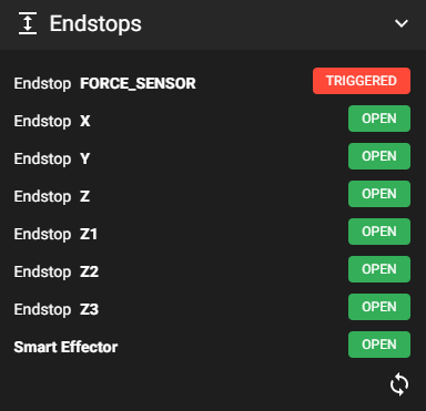
- Release the pressure, query, and ensure the endstop state again shows OPEN.
Force Sensor Probe Parameter Verification
The Vertigo Mk1 Bed Scrape function is similar to a nozzle probing action. The SCRAPE_BED macro does essentially the same thing as a probing move to a maximum travel distance. Either it completes the full travel or gets stuck on a part. If the scraper gets stuck on a part this means the part requires more force than the sensor is calibrated to provide; the sensor circuit is broken, the endstop triggers, and a number of retries will be attempted with user-specified pauses between them. If the part is still stuck after all the retries, the bed will return to a horizontal ‘ready state’, pause the queue, and prompt the user to clear the bed the old-fashioned way. Similar to previous testing, we will first check the the config values against the physcal system, do a “trial run,” then send it for the real thing.
- Run
PAUSEin the Console to get the toolhead out of the way. - Click the ‘DEBUG HOME Z’ button in the Calibration Panel in the Mainsail Dashboard. Again, do a sanity check that all 4 Z Joints are at the bottom of their travel and the Bed Lever is disengaged.
- Run
FORCE_MOVE_Z_REAR DISTANCE=1as a relatively save check that the Rear Z Joints are moving up and the bed is starting to tilt forward. - To get the bed vertical, run
FORCE_MOVE_Z_REAR DISTANCE=170. At this location it should be clear that the wedges on the Scraper Bar align with the Force Sensor Rocker. - Run
FORCE_MOVE_Z_REAR DISTANCE=20. The Scraper Modules should all be engaged, with razors touching the print surface. Here we can simulate a stuck part by pushing up from underneath one of the Scraper Wings (as close to the scraper’s linear guide carraige as you can get) and again querying the Endstops Panel to be extra certain that the Force Sensor will trigger through contact with the Scraper Bar. - Continuing our upwards journey, run
FORCE_MOVE_Z_REAR DISTANCE=200. This pushes the rear Z axis up to the defaultscrape_threshold_z_pos: 390. Past this point the bed is considered scraped and the Force Sensors function switches to ‘safety mode’, explained further in the next step. If the Force Sensors trigger at any point up to this value, retries will be attemped according to the config parameters, as referenced below.The last upward move will be calibrated. The default total distance from the endstop is
scrape_distance: 400. The console readout should showrear pair now +390.000 mm from nominal. Under normal operation, if for some reason the Force Sensors trigger between here and the previous distance, the bed is still considered fully scraped; the bed will return to ‘ready state’, and print queues will continue without issue. However because we are using a ‘FORCE_MOVE’ AND nearing the end of travel, some caution is required. - Run
FORCE_MOVE_Z_REAR DISTANCE=1and query the endstops for a trigger. Repeat until the scrapers are at the end of the bed or the FORCE_SENSOR endstop is TRIGGERED.- If the scrapers are at the end of the bed and the FORCE_SENSOR is OPEN -> Use the value in the readout
rear pair now +[value] mm from nominalfor the parameterscrape_distance:in printer.cfg. - In the unlikely event that FORCE_SENSOR is TRIGGERED -> subtract 7 from the value in the readout
rear pair now +[value] mm from nominaland use the result for the parameterscrape_distance:in printer.cfg.
The value of ~7mm comes from the designer’s testing and the long tolerance chain between the rear Z steppers and the Force Sensor circuit break.
It turns out that the Force Sensors can have something of a dual functionality. It is technically possible to raise the
scrape_distance:well beyond the physical upward travel limit of the rear Z axes, thus guaranteeing that the Force Sensors will trigger at the end of each bed scrape. Remember, above thescrape_threshold_z_pos:, this is considered a successful scrape and everything continues as normal. Ultimately, the designers decided to do it this way to hopefully reduce the repetitious load on the Z axes and increase the machines longevity, time between repairs, etc. Ideally, most parts become easier to release with cooling and require low force and few retries. However, if you’d rather get a free test of the Force Sensor functionality with each scrape, then that option is available. - If the scrapers are at the end of the bed and the FORCE_SENSOR is OPEN -> Use the value in the readout
- The bed has now achieved the dizzying heigts of Vertigo and would kindly like to be lowered back to earth. Oblige it by clicking ‘Home Z’ in the Toolhead Panel.
- Save printer.cfg and ‘FIRMWARE RESTART’.
Config Reference
printer.cfg
:
[force_sensor_probe]
endstop_name: force_sensor
pin: ^PA7                                # NC switch to GND: pullup, no invert
rear_steppers: stepper_z2, stepper_z3
front_steppers: stepper_z, stepper_z1
scrape_speed: 15.0                       # mm/s, rear-pair travel speed (up & down)
scrape_accel: 100                        # mm/s^2 for the isolated rear-only moves
scrape_threshold_z_pos: 390              # mm TOTAL travel; a trigger at/above this = fully scraped
scrape_distance: 400                     # mm full scrape travel; reaching it (trigger or not) = fully scraped (> threshold)
retries: 3                               # sub-threshold attempts allowed; REFILLS whenever an attempt digs deeper
retry_tolerance: 1.0                     # mm; a gain at/below this doesn't count as progress
max_total_attempts: 20                   # absolute safety cap on total attempts
delay_with_pressure: 1.0                 # s to dwell while still loaded, BEFORE retracting
delay_between_retries: 1.0               # s to dwell AFTER retract, before the next attempt
retract_distance: 5.0                    # mm to back off (descend) between retries
rehome_gcode: _HOME_Z_RAW
# on_scraped_gcode:                       # optional, runs after a successful scrape + home
on_failed_gcode: _SCRAPE_FAIL_MENU       # stuck below threshold -> blocking Mainsail prompt + PAUSE
Scrape Force Calibration
In the Force Sensors section of the Assembly Guide, we left off with ~2 full turns on the Force Sensor adjustment screw, or about ~1mm of compression. This is a good amount of force for continuity and functionality testing, but we’ll crank it up a bit now that we’re getting ready to scrape parts.
During initial testing, it was found that ~10-15 lbf (~44-65 N) per side is a good start for force needed to trigger the sensors. This should only require 1-2 additional full turns clockwise on each sensor adjustment screw. Remember, it shouldn’t require an enormous amount of force to eject parts. Press the sensors with your thumb and query the endstops to get an idea of the force being applied – use good judgement.
The adjustment on both sides must be equal.
Setting the Force Sensors too strong can prevent them from triggering when they should and possibly damage your printer.
Optional Procedure for Scrape Force Calibration:
- Power OFF the printer.
- Unscrew the Force Sensors from the frame.
- Remove the external wires from the WAGO connectors.
- Attach the leads from a multimeter to each WAGO connector, completing the circuit.
- Grab the most accurate scale you have.
- Turn the multimeter on and set it to ‘continuity mode’.
- Press the Force Sensor rocker onto the scale and note the weight at which the multimeter’s beep stops. In the US, you’re looking for ~10-15 lb, and for everywhere else, ~4.5-6.5 kg.
- Re-install the Force Sensors and power ON.
Bed Scrape Test
The ‘meat and potatoes’ of the Vertigo.
Here’s what to expect when this macro runs:
- The Z axes should home to the endstops, decoupling the bed from the Front Z Joints.
- The Rear Z Joints should move upwards and
- rotate the bed vertically,
- bring the Scraper Bar wedges into contact with the Force Sensors,
- and scrape the bed.
- When the full
scrape_distancehas been traversed, the Rear Z Joints should again home to the endstops, returning the bed to ~horizontal. - The bed should return to ‘ready position’, coupled with the Front Z Joints.
- Click ‘SCRAPE BED’ in the Part Ejection Panel in Mainsail.

- Give your Vertigo a high-five.
Config Reference
macros.cfg
:
[gcode_macro SCRAPE_BED]
Heaters
The extruder and bed contain heating elements and temperature sensors that are used to control them.
Now is a good time to sanity check that the temperature sensors are reading something close to ambient temperature; you may want to use an external thermometer if you are unsure. These can be found in the Temperatures Panel in Mainsail.
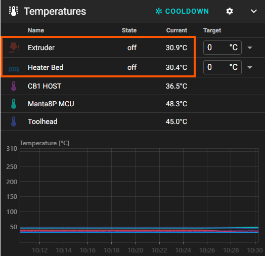
Extruder PID Tuning
PID Control is a widely used control algorithm. It works best when calibrated for a specific target. Kalico provides the option to save different PID tuning parameters to temperature-specific profiles.
Kalico also provides Model Predictive Control as an alternative to PID. This may become the default in future updates to the Vertigo config.
- First, let’s check that the heater actually heats and the temperature sensor measures the change. Set a safe target of 50°C in the Temperatures Panel. Since the PID is not calibrated for this target, there will be some oscillation around the target temperature. However, if you see no change, or change is measured in the wrong sensor, immediately power OFF and check your wiring and heater components.
- Assuming the nozzle is still on the plug, jog the toolhead +100 X to move it into the air.
- Click ‘❄️ COOLDOWN’ in the Temperatures Panel and check that the temperature starts to drop.
- In the Calibration Panel, click the dropdown next to ‘PID TUNE HEATER TEMPS’. The default settings will save PID tuning profiles for the extruder heater based on the temperature targets specified in the config, referenced below. The only change here is to set the fan power to 100%, as this is the most likely scenario during printing. Check the notes in macros.cfg for more information on how to customize this macro for your specific filament needs. When finished, the tuning macro will ‘SAVE CONFIG’ which restarts the firmware. Click ‘SEND’ to start.

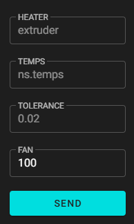
This macro may take half an hour or more to run. Have a ☕.
Config Reference
printer.cfg
:
[extruder]
:
## Extruder temperature
heater_pin: toolhead:EXT_HEATER
sensor_type: ATC Semitec 104NT-4-R025H42G
sensor_pin: toolhead:TH0
control = pid
pid_kp = 22.684
pid_ki = 2.881
pid_kd = 44.658
pid_version = 1
pid_target = 215.00
pid_tolerance = 0.0200
min_extrude_temp: 90
min_temp: 10
max_temp: 290
config_variables.cfg
:
[gcode_macro _MACRO_VARIABLES]
:
variable_pid_extruder_temps: [200, 220, 240, 260, 270]
:
macros.cfg
:
[gcode_macro PID_TUNE_HEATER]
Bed PID Tuning
PID control is quite sufficient for the bed. This is the same process as the extruder.
- Again, set a safe target of 50°C in the Temperatures Panel. The aluminum bed is a much larger thermal mass, so heating it will take substantially longer. Again, if you see no change, or change is measured in the wrong sensor, immediately power OFF and check your wiring and heater components.
- Click ‘❄️ COOLDOWN’ in the Temperatures Panel and check that the temperature starts to drop.
- In the Calibration Panel, click the dropdown next to ‘PID TUNE HEATER TEMPS’. This time, type ‘bed’ in the HEATER field, and make sure the fan power is set to 0. These settings will save PID tuning profiles for the bed heater based on the temperature targets specified in the config, referenced below. Click ‘SEND’ to start, and call a friend while the macro runs.
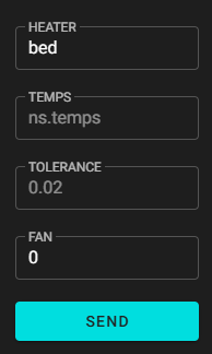
Config Reference
printer.cfg
:
[heater_bed]
heater_pin: PF5                          # SSR Pin - HE1
sensor_type: Generic 3950
sensor_pin: PB1
## Keep max_power within the SSR rating (Omron G3NA-210B-DC5 = 4A no heatsink):
##   4 / (bed_watts / mains_volts) = max_power   (cap at 1.0)
max_power: 1
min_temp: 0
max_temp: 125
control: pid
pid_kp: 58.437
pid_ki: 2.347
pid_kd: 363.769
config_variables.cfg
:
[gcode_macro _MACRO_VARIABLES]
:
variable_pid_bed_temps: [55, 70, 85, 105]
:
macros.cfg
:
[gcode_macro PID_TUNE_HEATER]
Resonance Compensation
Resonance compensation is a deep subject, but basically everything is a spring. The [input_shaper] module is a relatively sophisticated attempt to mitigate some of the cosmetic defects or “vertical fine artifacts (VFA)” in printed parts by compensating for this ‘springy-ness’.
- Ensure all axes are homed.
- In the Console, run
SHAPER_CALIBRATE. - Click ‘SAVE CONFIG’ at the top of the Mainsail Dashboard, or run
SAVE_CONFIGin the console.
To learn more about measuring and compensating for resonance, read Kalico Docs > Tuning.
Config Reference
printer.cfg
:
[input_shaper]
shaper_type_x = mzv
shaper_type_y = mzv
shaper_freq_x = 66.4
shaper_freq_y = 47.0
Bed Leveling (Z Tilt) Test
Due to the inherent impreceision of homing to four different Z endstops, decoupling the bed from the front Z axes and rotating the bed vertically, the ability to automatically level the bed is an essential feature of the Vertigo Mk1. During the bed leveling macro:
- The nozzle will heat to the printing temperature.
- The toolhead will wipe and plug the nozzle.
- The part cooling fans will turn on to help the nozzle cool quickly to the filament vitrification temp (below its melting point) to prevent ooze.
- The toolhead will cycle through 3 probing points (3 points define a plane), each near a kinematically constrained pivot point for the bed, sampling each point several times to measure an average Z position.
- After each iteration, the Z axes will adjust independently to reduce the deviation in measured average Z positions.
- Either the deviation will converge to a value below the tolerance specified in the config – meaning the bed is level – or it will report the failure to converge as an error in the Console.
Click the dropdown next to ‘LEVEL BED’ in the Calibration Panel. To speed things up a bit, enter the lowest extruder temperature with a previously calibrated tuning profile, i.e. 200°C in the EXTRUDER_TEMP field and a value just below that, i.e. 195°C in the VITRIFICATION_TEMP field. Click ‘SEND’ to start.

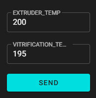
If the bed leveling procedure fails to converge, refer to the troubleshooting steps in the Nozzle Probe section above.
Config Reference
printer.cfg
:
[z_tilt]
# Pivot points (nozzle coords) where the bed attaches to each Z stepper, in
# stepper order: stepper_z, stepper_z1, stepper_z2, stepper_z3. The front pair
# shares a pivot (flexible lever bar at center-front).
z_positions:
    125, -18
    125, -18
    2, 283
    242, 283
# Probe points for Z_TILT_ADJUST (nozzle coords; probe must be over the bed).
points:
    125, 5
    5, 203
    245, 203
speed: 200
horizontal_move_z: 10
retries: 4
retry_tolerance: 0.010
macros.cfg
:
[gcode_macro LEVEL_BED]
Global Z Offset
The goal here will be to get a baseline Z offset that should allow for some calibration prints for fine tuning. We’ll be doing the old-school, tried-and-true paper test method. So grab your favorite piece of paper and let’s go.
- If you haven’t just done the Bed Leveling section, do it now.
- Send the nozzle to approximately the middle of the bed:
G90thenG1 X125 Y105 F6000. - Place the pieice of paper on the bed, under the nozzle. You may remove the Cowl if necessary (or just get a bigger piece of paper).
- In the Console, run
PROBE_CALIBRATE. After an initial probing move, the ‘Manual Probe’ tool will appear. - Use the ‘Manual Probe’ tool to raise the bed until there is just a bit of friction when moving the piece of paper.
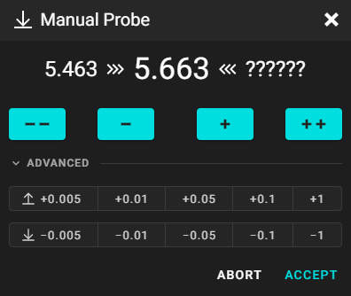
- Click ‘ACCEPT’ then ‘SAVE CONFIG’ at the top of the Mainsail Dashboard (or run
SAVE_CONFIGin the Console).
Config Reference
printer.cfg
:
[smart_effector]
:
z_offset: 0
:
Camera Options
There are essentially two options for the camera config in crowsnest.conf:
- Image Quality: High resolution -> High Bandwidth Usage, High Latency
crowsnest.conf : [cam 1] mode: ustreamer # https://docs.mainsail.xyz/crowsnest/faq/backends # mode: camera-streamer # Use for low latency with smaller resolution below port: 8080 # HTTP/MJPG stream/snapshot port device: /dev/video0 # See log for available devices resolution: 2592x1944 # <width>x<height> format # resolution: 640x480 # use for low latency 'real time' video with streamer above max_fps: 5 # if hardware supports it, it will be forced, otherwise ignored/coerced. v4l2ctl: brightness=-20,contrast=20,power_line_frequency=2 # Add v4l2-ctl parameters to set up your camera, see log for your camera capabilities. custom_flags: --drop-same-frames=30 - Real-Time Video: Low resolution -> Low Bandwidth Usage, Low Latency (default)
crowsnest.conf
:
[cam 1]
# mode: ustreamer                         # https://docs.mainsail.xyz/crowsnest/faq/backends
mode: camera-streamer                   # Use for low latency with smaller resolution below
port: 8080                              # HTTP/MJPG stream/snapshot port
device: /dev/video0                     # See log for available devices
# resolution: 2592x1944                   # <width>x<height> format
resolution: 640x480                     # use for low latency 'real time' video with streamer above
max_fps: 5                              # if hardware supports it, it will be forced, otherwise ignored/coerced.
v4l2ctl: brightness=-20,contrast=20,power_line_frequency=2     # Add v4l2-ctl parameters to set up your camera, see log for your camera capabilities.
# custom_flags: --drop-same-frames=30
You can change
power_line_frequency=2topower_line_frequency=1if you are on a 50Hz electrical grid.These are all the available v4l2ctl parameters for the Vertigo camera:
vertigo@vertigo-host:~ $ v4l2-ctl -d /dev/video0 --list-ctrls

User Controls

                    brightness 0x00980900 (int)    : min=-64 max=64 step=1 default=-5 value=-20 flags=has-min-max
                      contrast 0x00980901 (int)    : min=0 max=100 step=1 default=50 value=20 flags=has-min-max
                    saturation 0x00980902 (int)    : min=0 max=100 step=1 default=64 value=70 flags=has-min-max
                           hue 0x00980903 (int)    : min=-180 max=180 step=1 default=0 value=0 flags=has-min-max
       white_balance_automatic 0x0098090c (bool)   : default=1 value=1
                         gamma 0x00980910 (int)    : min=100 max=500 step=1 default=300 value=300 flags=has-min-max
          power_line_frequency 0x00980918 (menu)   : min=0 max=2 default=1 value=2 (60 Hz)
     white_balance_temperature 0x0098091a (int)    : min=2800 max=6500 step=10 default=4600 value=4600 flags=inactive, has-min-max
                     sharpness 0x0098091b (int)    : min=0 max=100 step=1 default=50 value=50 flags=has-min-max
        backlight_compensation 0x0098091c (int)    : min=0 max=2 step=1 default=0 value=0 flags=has-min-max

Camera Controls

                 auto_exposure 0x009a0901 (menu)   : min=0 max=3 default=3 value=3 (Aperture Priority Mode)
        exposure_time_absolute 0x009a0902 (int)    : min=50 max=10000 step=1 default=166 value=166 flags=inactive, has-min-max
    exposure_dynamic_framerate 0x009a0903 (bool)   : default=0 value=0
                  pan_absolute 0x009a0908 (int)    : min=-57600 max=57600 step=3600 default=0 value=0 flags=has-min-max
                 tilt_absolute 0x009a0909 (int)    : min=-43200 max=43200 step=3600 default=0 value=-3600 flags=has-min-max
                focus_absolute 0x009a090a (int)    : min=0 max=1022 step=1 default=68 value=260 flags=has-min-max
    focus_automatic_continuous 0x009a090c (bool)   : default=1 value=0
                 zoom_absolute 0x009a090d (int)    : min=0 max=3 step=1 default=0 value=0 flags=has-min-max