Z Endstops
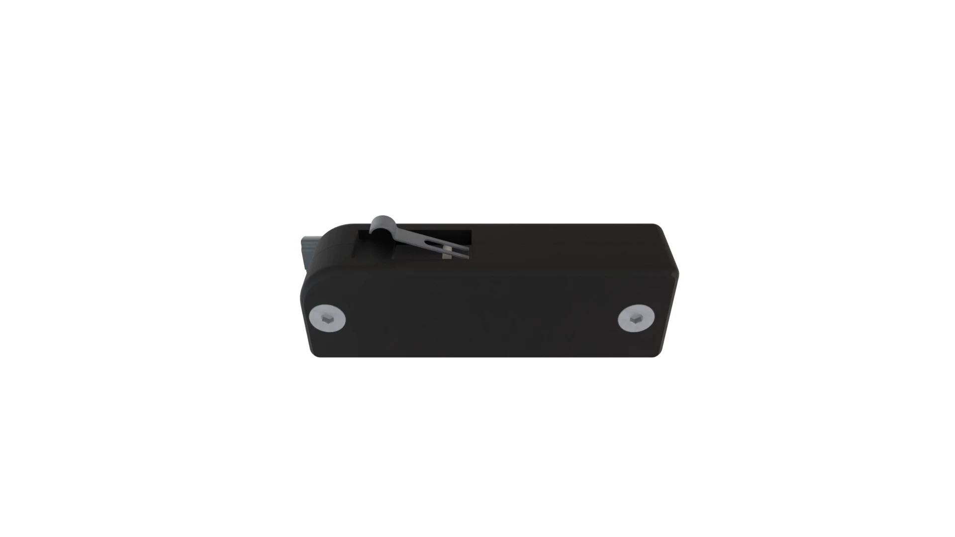
This is the first section where cables are installed, so it’s a good time to check out the section of the Wiring Guide: Understanding the Wiring Diagram & Cable Spec
Materials
| Hardware (for 1 of 4 pods) | Qty |
|---|---|
| Z Endstop Switch PCB | 1 |
| M3 Roll-In Nut | 2 |
| M3x20 FHCS | 2 |
| Cables |
|---|
| Z-68 |
| Z-69 |
| Z-70 |
| Z-71 |
| Printed Parts | Qty |
|---|---|
| Cable Cover 10mm | 2 |
| Cable Cover 25mm | 4 |
| Cable Cover 55mm | 2 |
| Cable Cover 240mm | 2 |
| Cable Gutter - Z Endstop Center | 1 |
| Z Endstop Pod | 4 |
| Z Endstop Pod Cap | 4 |
Animated Assembly
Assembly Notes
0:15 These are NOT the cables that come in the packages with the endstop PCBs. The correct cables will be labeled and packaged with the rest of the cable bundles.
- 0:24 Sandwich the Z Endstop Switch PCB between the Z Enstop Pod and Z Endstop Pod Cap, ensuring the wires route around the screw stud. A tiny dab of glue can be used to keep the pod and cap together if it’s an issue during install.
- 0:53 This step is only for aligning the Z Endstop Pod, not for adjusting the height of the Z Joint at endstop trigger.
- 1:37 These two cable covers are separate because the 9mm belt attached to this tensioner runs close to the extrusion. The gap between these cable covers should roughly match the gap in the tensioner where the 9mm toothed idler sits.
- 2:16 The Z Endstop Pods will need to be installed with the mounting FHCS screws entering from the other side when installed on side A. They are designed with this “symmetry” in mind – also noted at 2:26.
Z Endstop Cable Location - Top View
            Rear
      Z-70 ------ Z-71
        |          |
 Side A |          | Side B
        |          |
      Z-68 ------ Z-69
            Front