Force Sensors
Materials
| Hardware (for each sensor) | Qty |
|---|---|
| WAGO Connector - 2-Pin | 2 |
| M5x20 Dowel Pin | 2 |
| Die Spring | 1 |
| Magnet Cube | 1 |
| Magnet 6mm x 3mm | 2 |
| Makerbeam XL T-Nut | 1 |
| M3x45 SHCS (Stainless) | 1 |
| M3x5.7 Brass Insert | 1 |
| M3x12x1 Oversized Washer | 2 |
| M3x7x0.5 Washer | 5 |
| M4x12x1 Washer | 2 |
| M4x12x1 Nylon Washer | 2 |
| Wave Spring Washer | 2 |
| M3 Nyloc Nut | 2 |
| M3 Cap Nut (Acorn Nut) | 1 |
| PTFE Tube - 3mm ID x 4mm OD (cut from long piece) | 10mm |
| Cables - Side A |
|---|
| Z-60 |
| Z-73 |
| Z-74 |
| Cables - Side B |
| Z-61 |
| Z-75 |
| Z-76 |
| Printed Parts | Qty |
|---|---|
| Force Sensor Frame Mount A | 1 |
| Force Sensor Frame Mount B | 1 |
| Force Sensor Plug | 2 |
| Force Sensor Rocker | 2 |
| Force Sensor Washer Setting Tool | 1 |
Animated Assembly
Assembly Notes
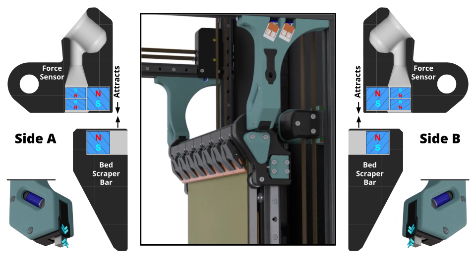
- 0:29 See the magnet polarity information below. We will make sure the magnets in the Bed Scraper Bar attract to the Force Sensors when we get to that section.
- 0:41 These two magnets are a just a low profile way of retaining the more powerful cube magnet just installed.
- 1:54 Compression of wave spring washers is not to scale.
- 2:13 The PTFE will need to be cut from the long section of 3mm ID tube in the kit.
- 2:19 You may need to hold the PTFE (gently with pliers if necessary) and screw the M3 into it if it doesn’t slide on.
- 2:40 The gap here is just to see that the PTFE stays up against the M3 washer on the left when the brass insert is threadlocked in place.
- 2:46 Threadlocker or glue of your choice will work fine.
- 3:07 ~2-3mm should do. This is just to make some room in the printed tool in the next step.
- 3:44 Ensure not to move Nyloc when fastening the cap nut.
- 3:50 Relax the spring, but not entirely. The T-nut should have ~2 full rotations of compression on the spring.
3:29 The principle function of this tool is to set the position of the Nyloc nut on the right, such that the fixed wwasher is 32.6mm from the same-sized washer on the other side, which also has a locating feature in the tool. The tool acts like a wrench for the Nyloc, so the nut should not rotate when the screw is turned. As the M3 is screwed into the Nyloc, the play (gap) between the Nyloc and the fixed washer is closed, eventually pushing the other washer up against its locating feature. When that happens, we’re ready to move on and lock the fixed washer in place from the other side. Below is a more in-depth look at how the tool should be used.
- 3:47 Decompress until the spring is only compressed ~1mm from full extension. The proper force will be calibrated in the Checks and Calibration section.
- 4:33 Remove support material from Force Sensor Plug.
- 5:12 Force Sensor Frame Mount should touch the rear vertical extrusion.
- 5:15 Side B Force Sensor can be assembled now, but wait to install it until the Routing Pod section. Continue to Y Endstop
The compression force of the ‘sensors’ will be adjusted in the Checks and Calibration section. Part of the complexity in the design of the ‘force sensors’ was to ensure that they could be:
- adjusted for compression force without disassembly
- made from cheap, off-the-shelf components, commonly found in 3D printers
- repeatable after install, particularly with regard to the wire routing and conducting contacts
Magnet Polarity
Continuity Testing
Preprequisite:
- Set multimeter to continuity mode
- Multimeter continuity mode tested and working (beeps when touching leads)
Test:
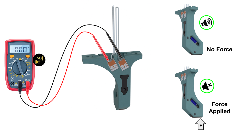
- Insert the multimeter leads into the Wago connectors as shown.
- With no force applied to the rocker, the multimeter should beep.
- Apply force to the rocker. The beeping should stop, indicating the connection is broken.
- Release the rocker. The multimeter should beep again, confirming the connection has returned.
Pass: The multimeter beeps with no force, stops beeping when force is applied, and beeps again when the force is released.