Wiring
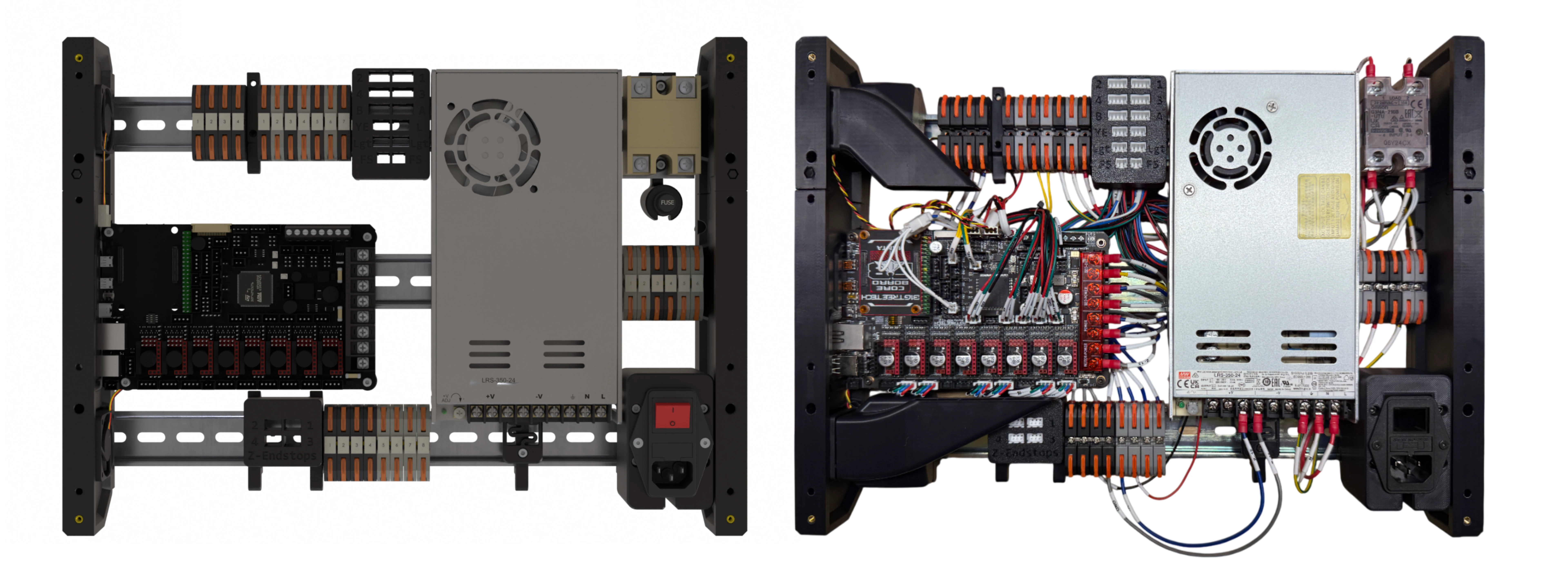
Before You Start
The goal of this guide is to help you wire the printer carefully and consistently. That said, electricity can be dangerous. Incorrect wiring or unsafe work practices can cause injury, damage components, start a fire, or worst of all, frighten your kitty. You’ve got this — take your time, work safely, don’t skip steps, and double-check each step before moving forward.
This printer is a DIY kit assembled from parts sourced from many suppliers across the world. Because of this, hardware details may vary between supplier batches or self-sourced parts. This can include component pinout, wire colors, connector styles, and other small differences. Be careful about making assumptions based on appearance alone. This guide provides the tools needed to verify each part, cable, and connection using the specification documents, which will be explained in the next section.
Some image text may appear small on this page. For a larger view, right-click the image and select “Open image in new tab”.
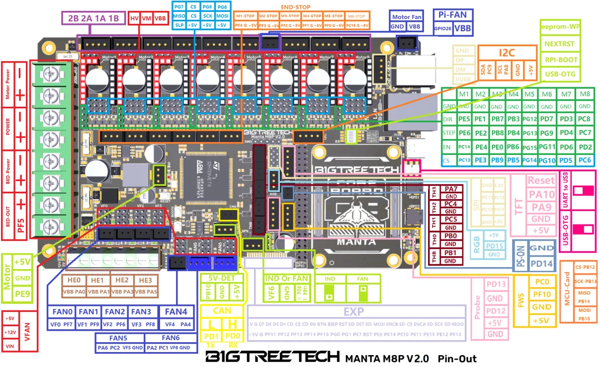
BigTreeTech Manta M8P V2 Documentation contains information related to the printer controller (mainboard). For convenience, here’s the M8P V2 Pinout.
Mellow FLY SHT36 V3 Documentation contains information related to the toolhead board. For convenience, here’s the FLY SHT36 V3 Pinout
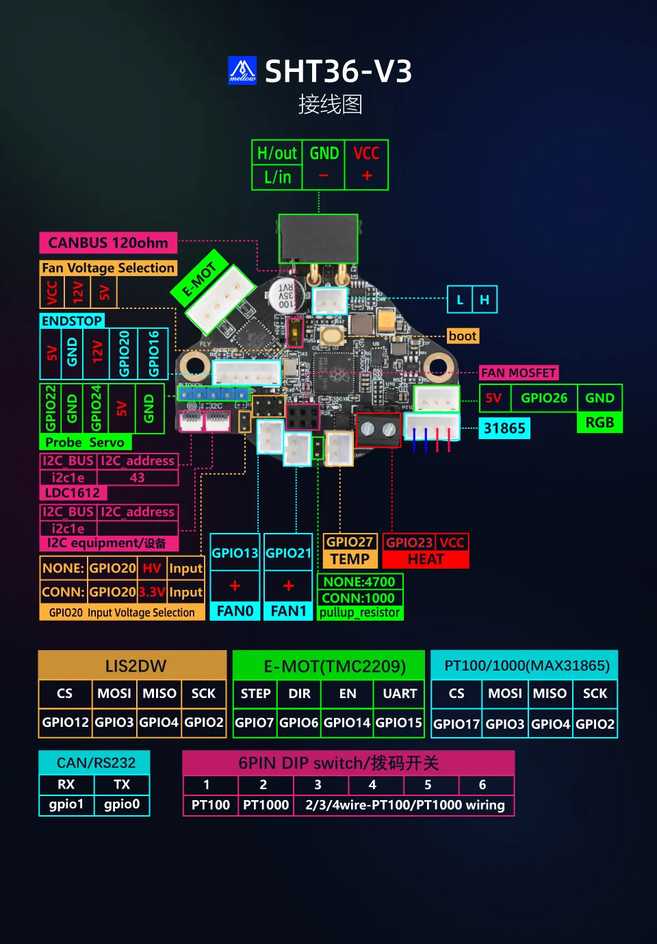
Table of Contents
- Wiring
- Before You Start
- Table of Contents
- Understanding the Wiring Diagram and Cable Spec
- Diagrams of Peripheral-Board Connections, Z-Codes, and Schematic Labels
- Configuring the Toolhead Board
- Wiring The Electronics Backpack
- 1. Install CM and Heatsink
- 2. Install Jumpers on Main Board
- 3. Install Stepper Drivers
- 4. Install Terminal Block Bus Bars
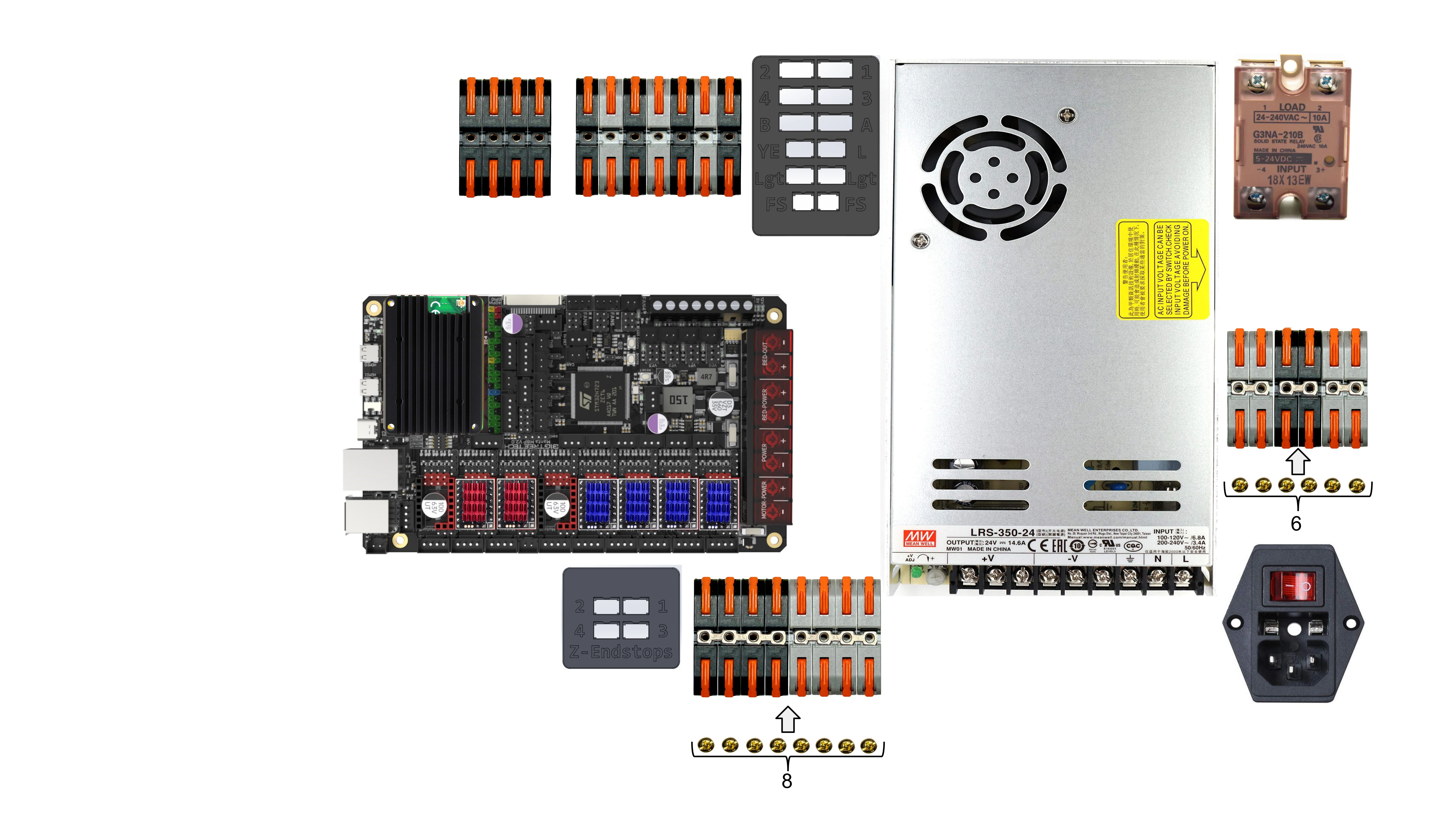
- 5. Install Terminal Block Bus Bar Fasteners
- 6. Install Terminal Block Number Covers
- 7. Check Fuse Amperage - IEC C14 Plug
- 8. Check Fuse Amperage - Bed Fuse (Z-07)
- 9. Check PSU’s AC Input Voltage Switch
- 10. Install Cables: Z-01, Z-02, Z-03, Z-11, Z-12
- 11. Install Cables: Z-04, Z-05, Z-06
- 12. Prepare Multimeter for Continuity Checks
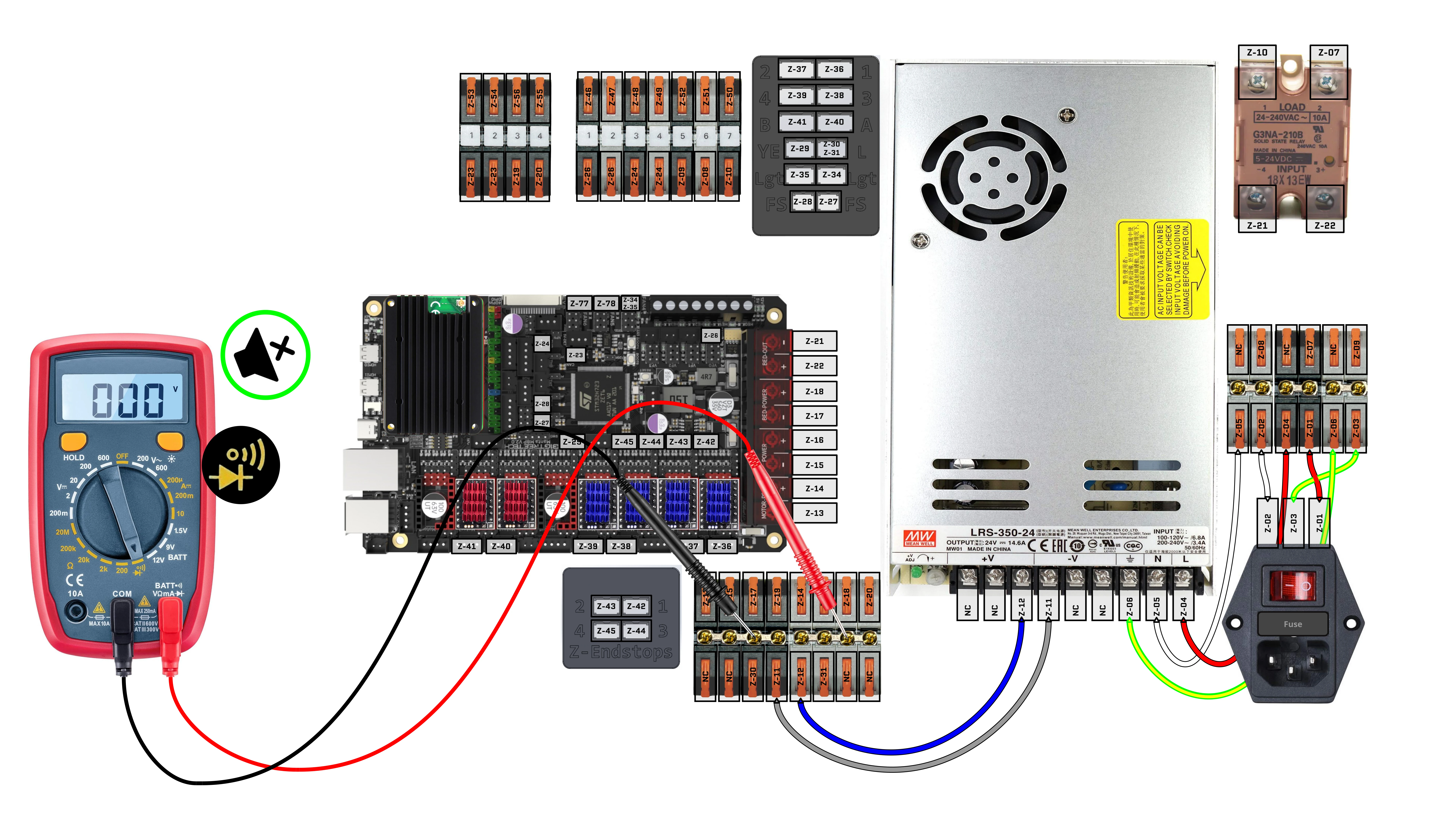
- 13. Check for short between AC Live (L) and AC Neutral (N)
- 14. Check for short between AC Neutral (N) and AC Earth (⏚)
- 15. Check for short between AC Live (L) and AC Earth (⏚)
- 16. Check for short between PSU’s DC(+) and DC(-)
- 17. Check for continuity between IEC C14 plug and PSU for AC Live (L)
- 18. Check for continuity between IEC C14 plug and PSU for AC Neutral (N)
- 19. Check for continuity between IEC C14 plug and PSU for AC Earth (⏚)
- 20. Preparing for First Power ON
- Always prioritize your safety and the safety of those around you
- 21. Adjusting PSU to 24V
- 22. Install Terminal Block Covers
- 23. Install Cables: Z-13, Z-15, Z-17, Z-19
- 24. Install Cables: Z-14, Z-16, Z-18, Z-20
- 25. Install Cables: Z-07, Z-08, Z-09, Z-10, Z-21, Z-22
- 26. Install Cables: Z-23, Z-24, Z-26
- 27. Assembling Peripheral Blocks
- 28. Install Cables: Z-42, Z-43, Z-44, Z-45
- 29. Install Cables: Z-27, Z-28
- 30. Install Cables: Z-34, Z-35, Z-32/33
- 31. Install Cables: Z-29, Z-30, Z-31
- 32. Install Cables: Z-40, Z-41
- 33. Install Cables: Z-38, Z-39
- 34. Install Cables: Z-36, Z-37
- 35. Complete the Electronics Backpack Section then Continue
- 36. Install Cables: Z-25, Z-48, Z-49, Z-53, Z-54, Z-55, Z-56, Z-60, Z-61, Z-114
- 37. Unplug Toolhead’s XT30 Connector
- 38. Checking Toolhead Power
- 39. PZ Probe Controller Cable: Z-105, Z-106, Z-107
- 40. Install Lights, Endstops, Electronics Fans, Camera: Z-57, Z-58, Z-59, Z-68, Z-69, Z-70, Z-71, Z-72, Z-77, Z-78, Z-116
- 41. Endstop Check
- 42. Electronics Fans Pinout Check: Z-77, Z-78
- 43. Install Bed Heater, Bed Fans: Z-46, Z-47, Z-50, Z-51, Z-52
- 44. Install Stepper Motors: Z-46, Z-47, Z-50, Z-51, Z-52
- Continue to the Firmware Guide
Understanding the Wiring Diagram and Cable Spec
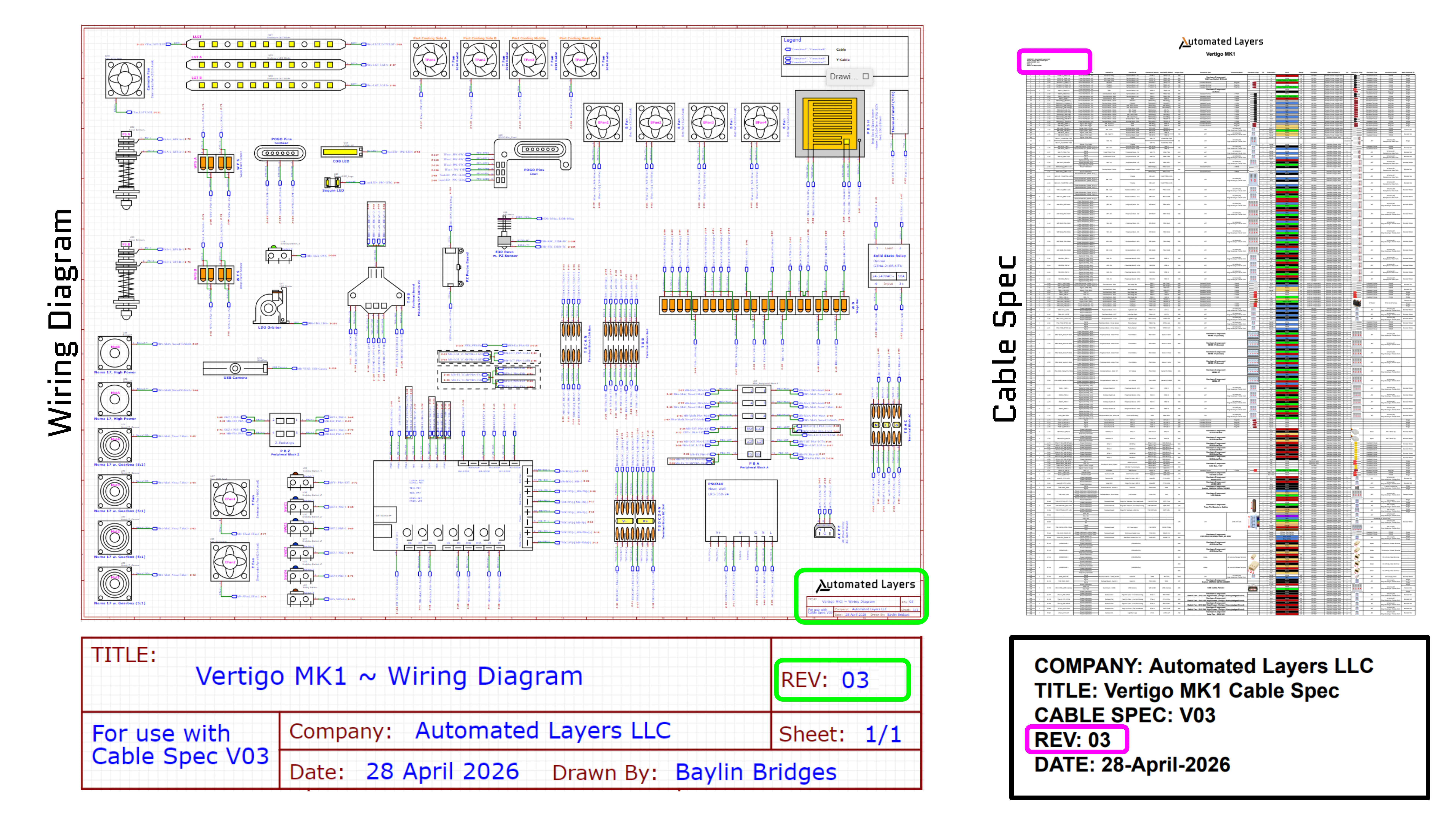
Wiring is defined by two core documents: the wiring diagram and the cable specification.
The Cable Specification
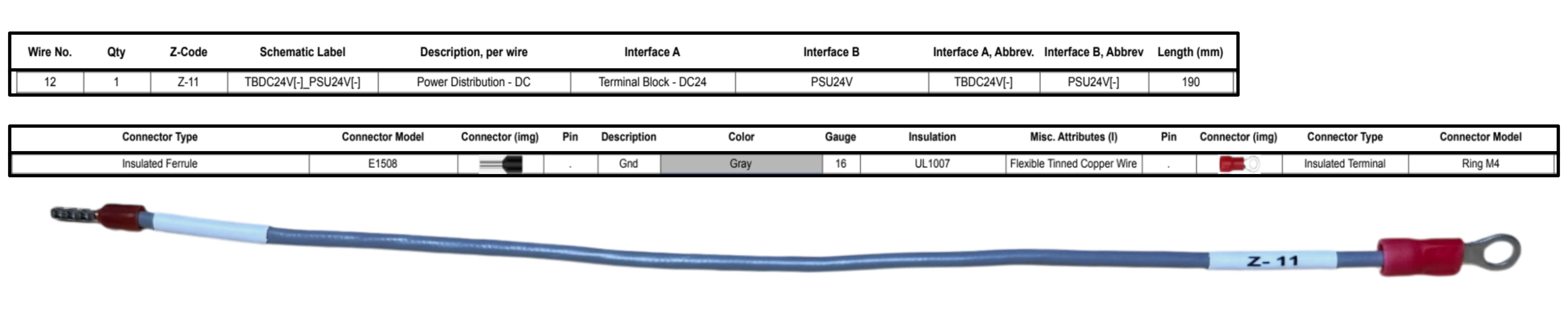
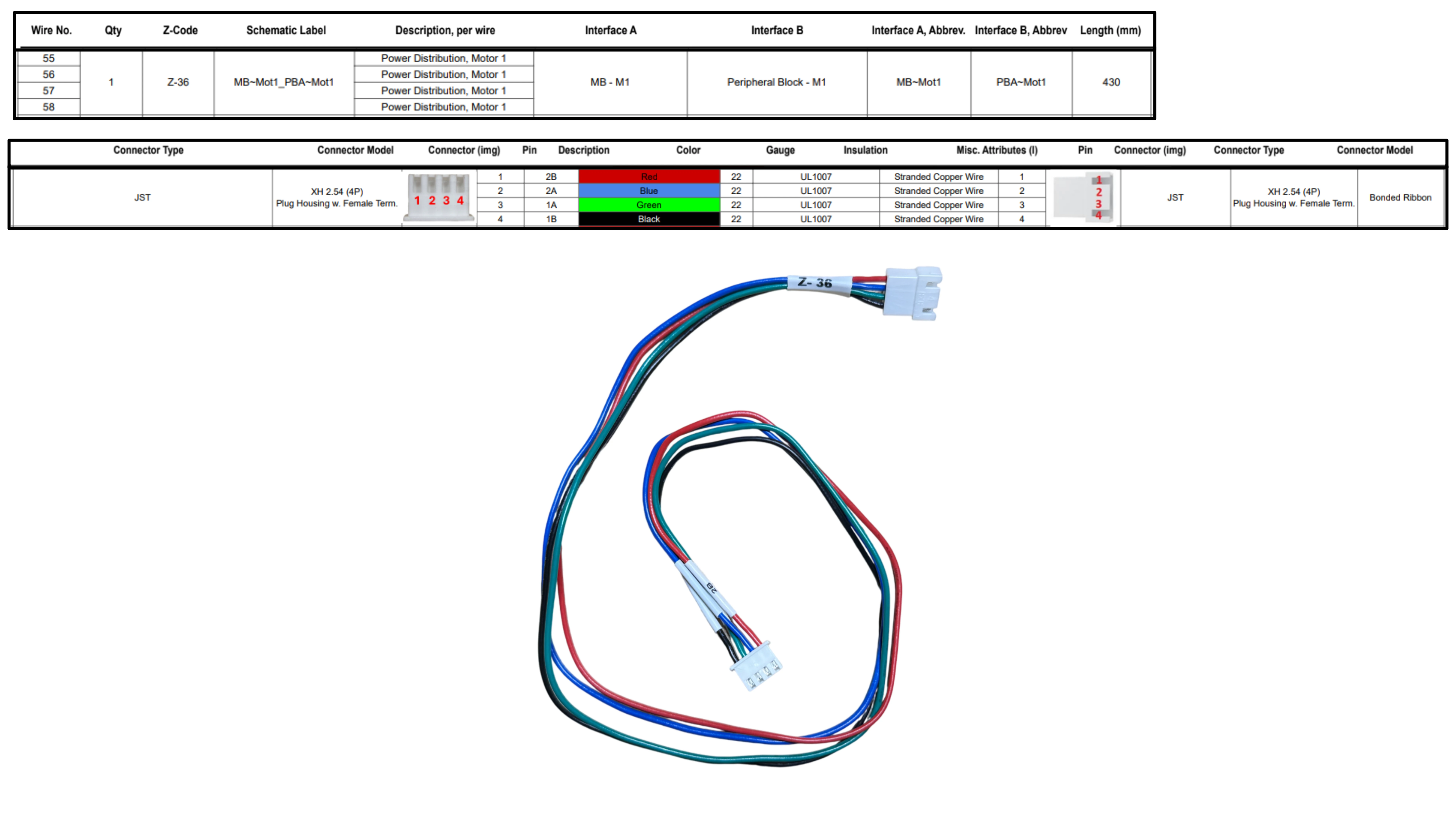
This document defines how each cable is manufactured, including its Z-code, length, wire gauge, color, pinout, and other relevant build details.
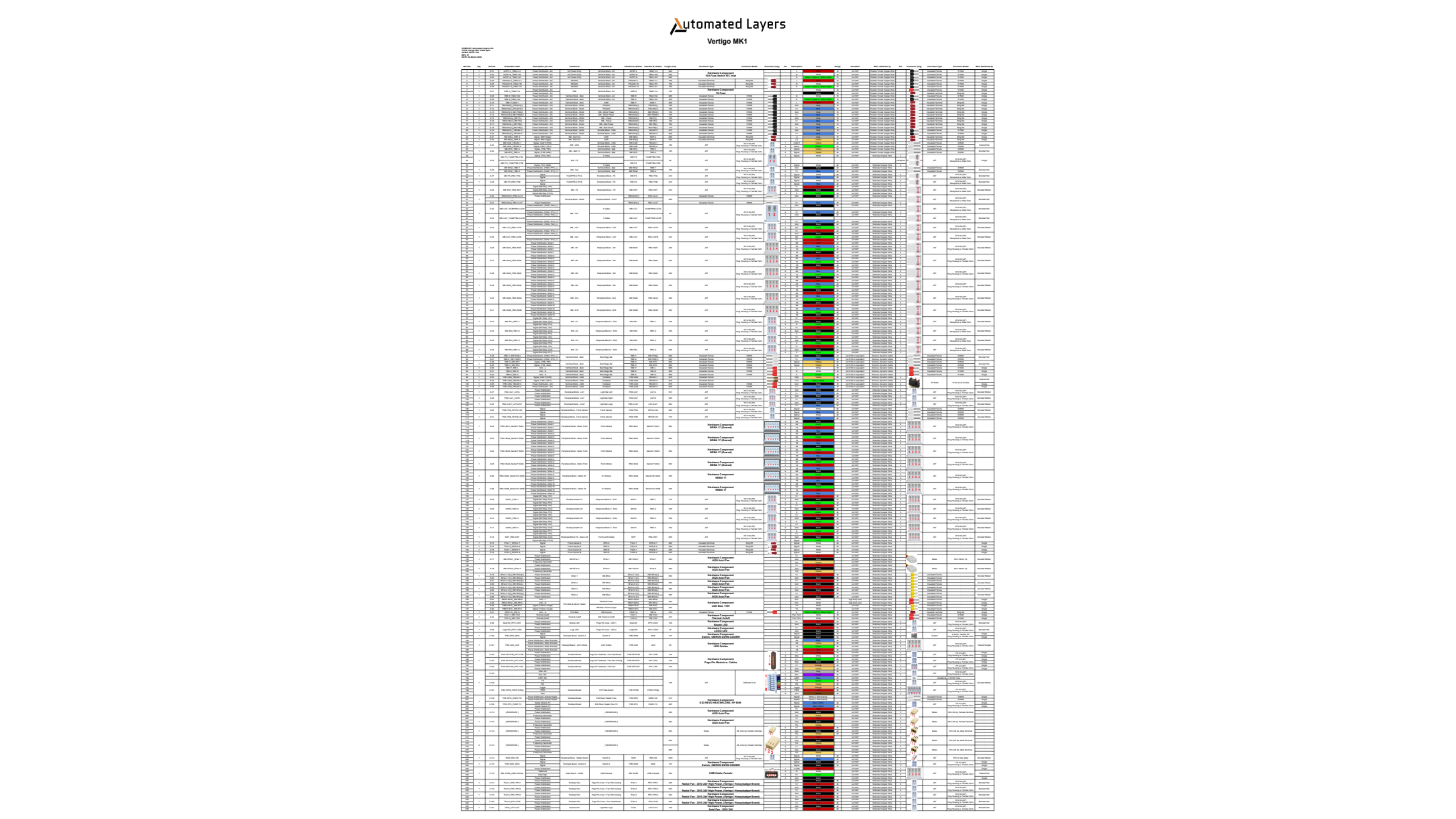
Cable Construction Examples
Below are cables Z-11 and Z-36 as it appears in the cable specification, along with a photos of the construction for reference. Keep in mind that not every hardware component will have the physical Z-code label attached. In those cases, identify the cable by comparing its features to the cable specification, or consult the Wiring Diagram if you know where the component is being installed to easier identifiy the Z-code.
The Wiring Diagram
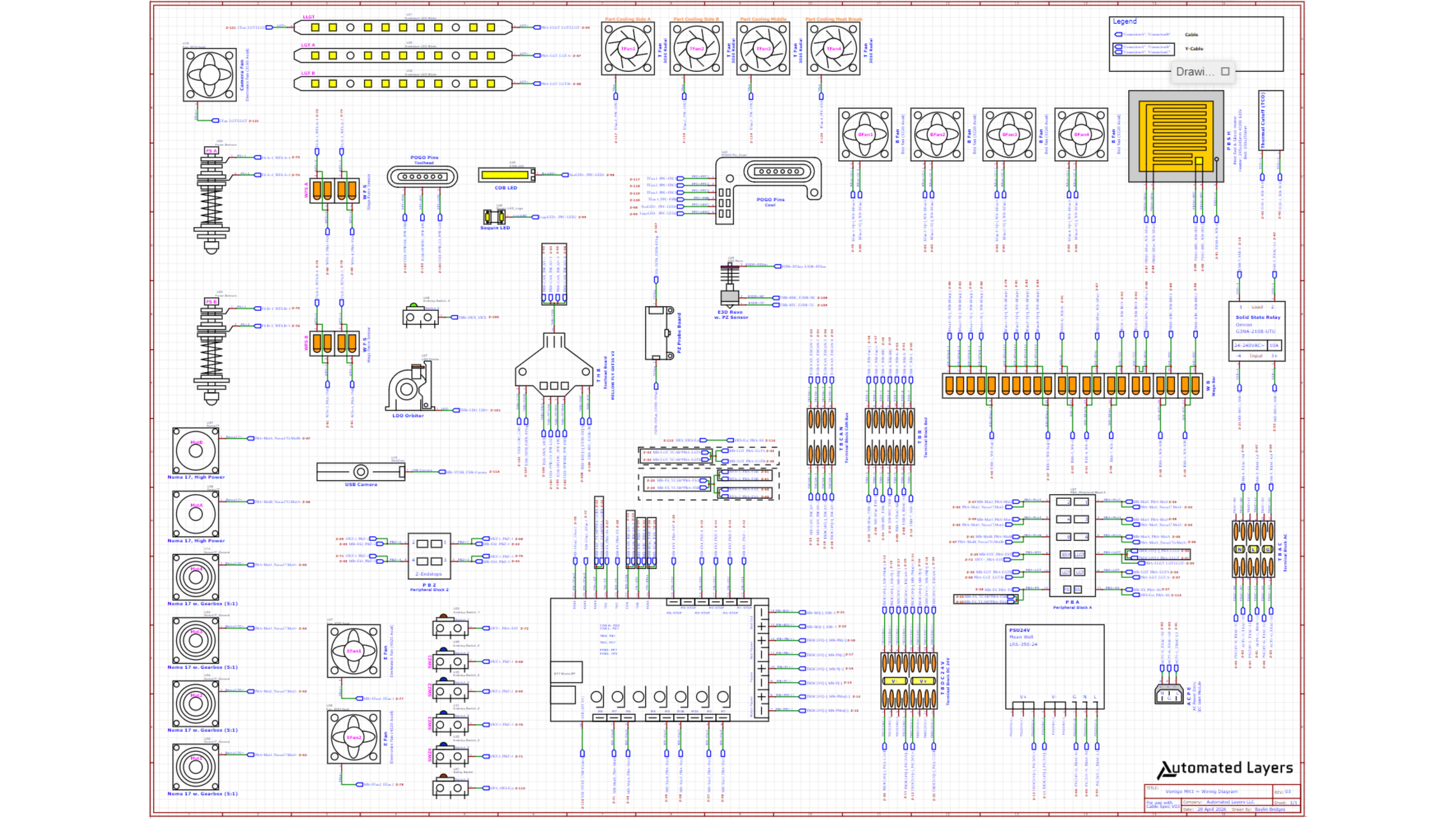
This document defines how the cables terminate within the system, using symbols and Z-codes to identify connections.
Finding Z-Code Termination Points Example
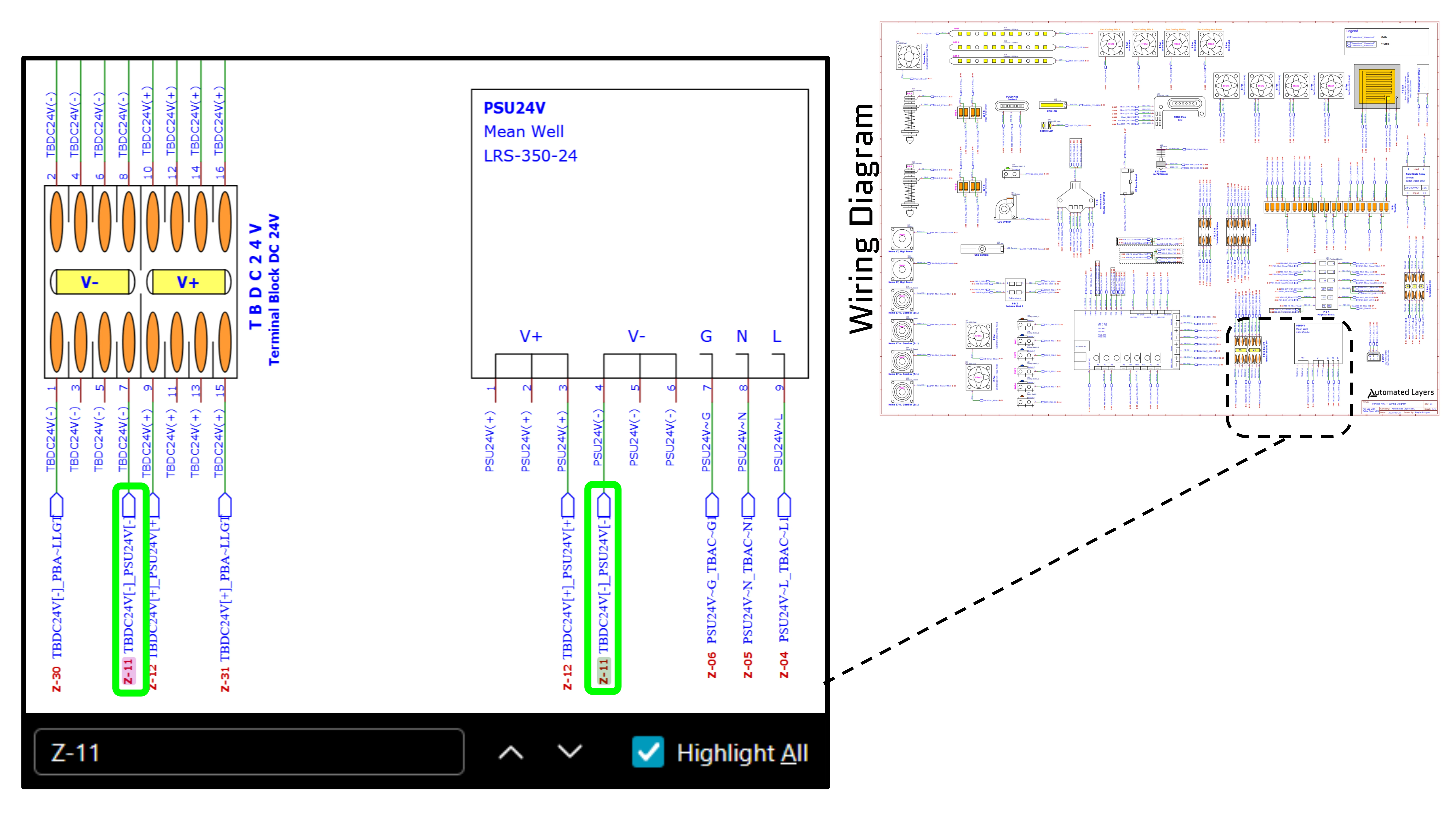
- Locate the Z-Code: There will be one located at each termination point for the cable
- Note the schematic label: This indicates the termination points using abbreviated names, separated by an underscore “_”
- E.g. Z-11, TBDC24V[-]_PSU24V[-] indicates you can find the termination points at Terminal Block DC 24V [-] and the Power Supply Unit 24V [-]
Tip: Opening the PDF and using the find function is an easy way to navigate the Z-Code termination points.
When using these documents, always perform a quick check to confirm that you are using the latest revision before proceeding.
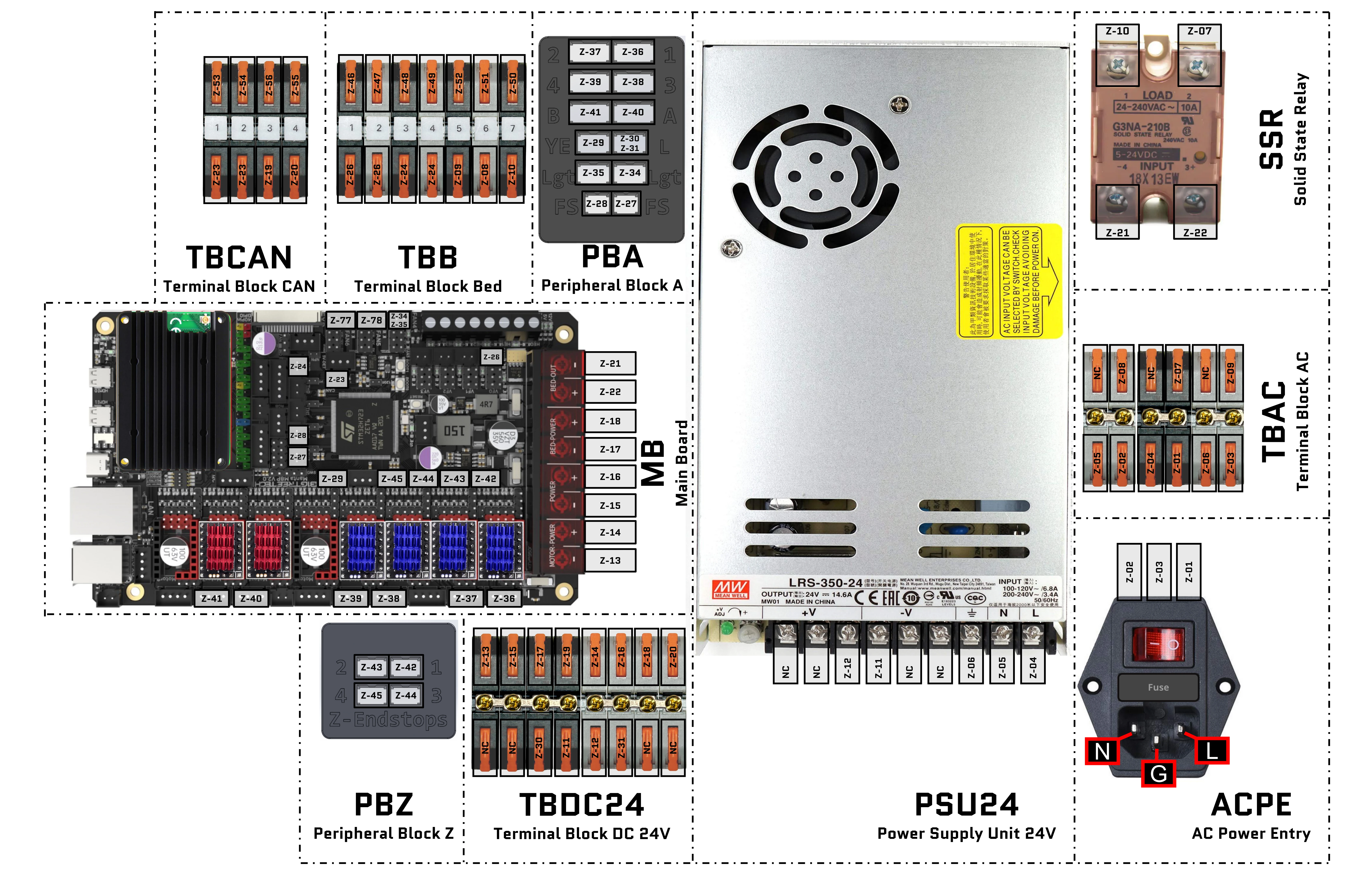
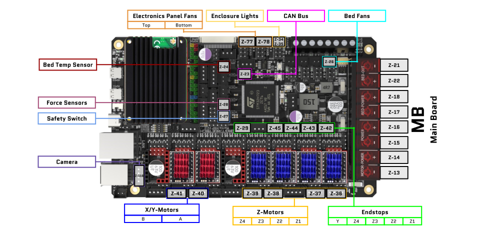
Diagrams of Peripheral-Board Connections, Z-Codes, and Schematic Labels
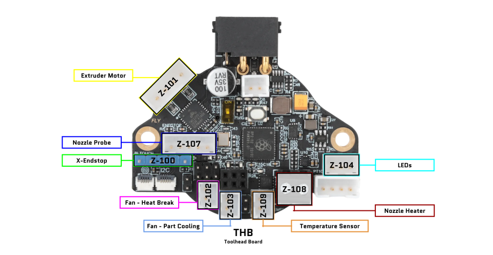
Configuring the Toolhead Board
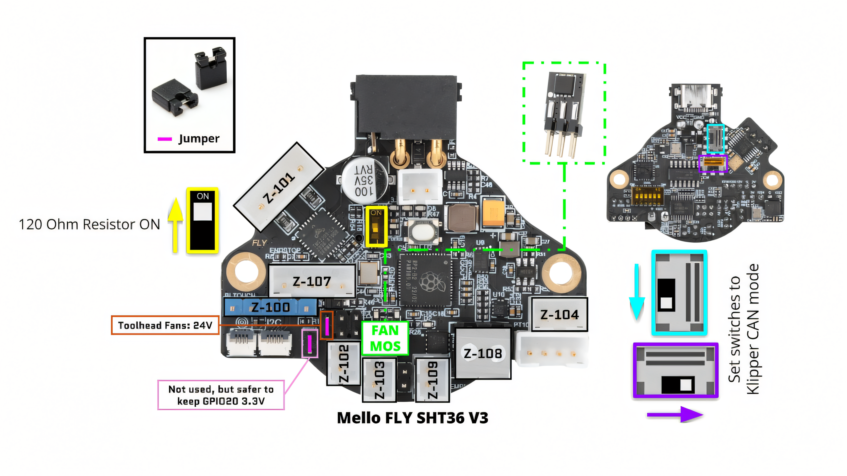
Install Jumpers and Fan Mosfet and Set Switches (for CAN Mode) on Toolhead Board
- Toolhead fans are set to 24V
- Setting GPIO20 to 3.3V is optional, but recommended
- Fan Mosfet is installed (Mosfet can be installed either orientation; just ensure all 6 pins are inserted)
- Toolhead board is set to CAN mode with switches on back of board
- Set CAN Bus 120 Ohm terminal resistor to ON position
Return to Extruder Plate assembly
Wiring The Electronics Backpack
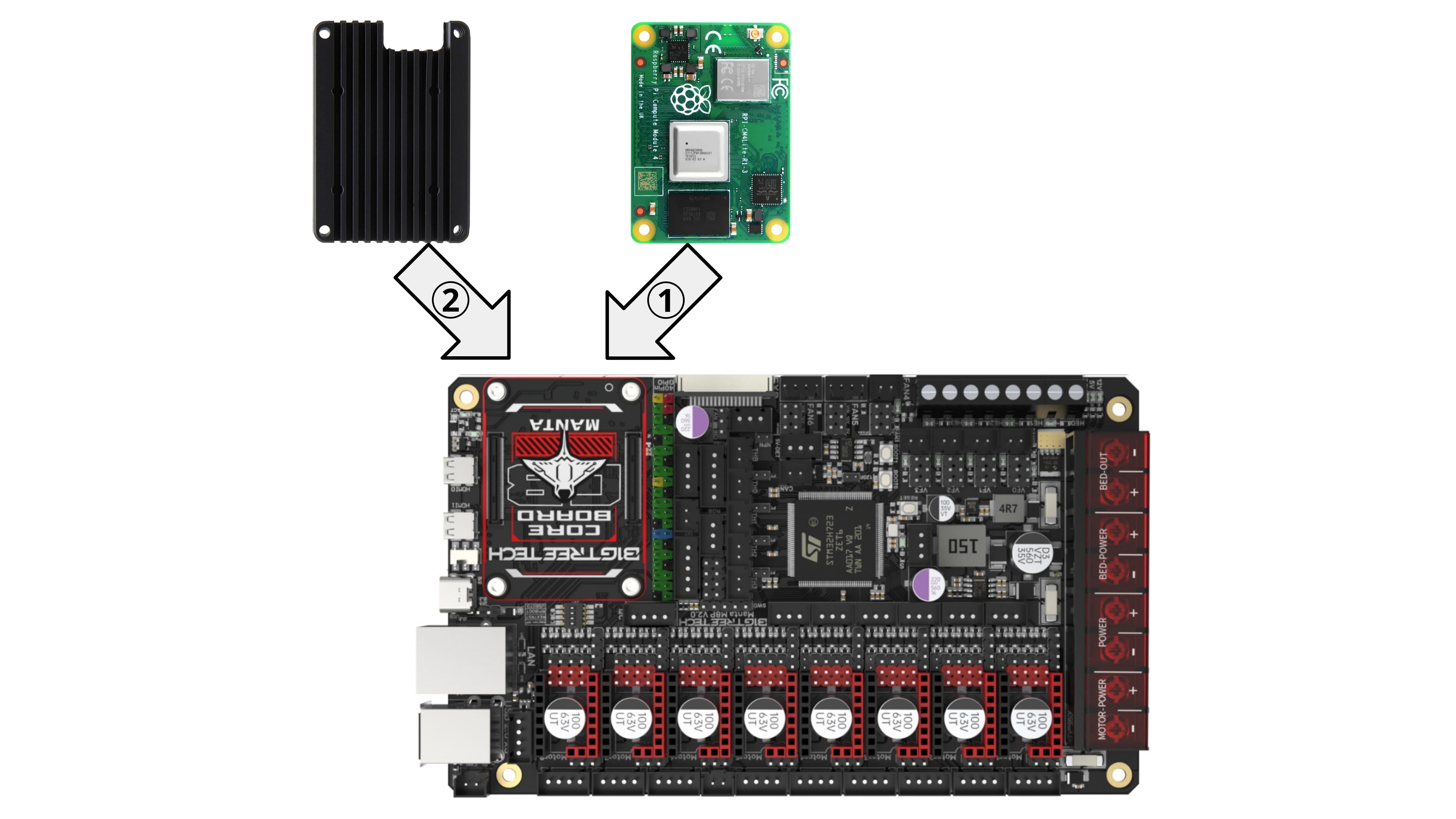
1. Install CM and Heatsink
2. Install Jumpers on Main Board
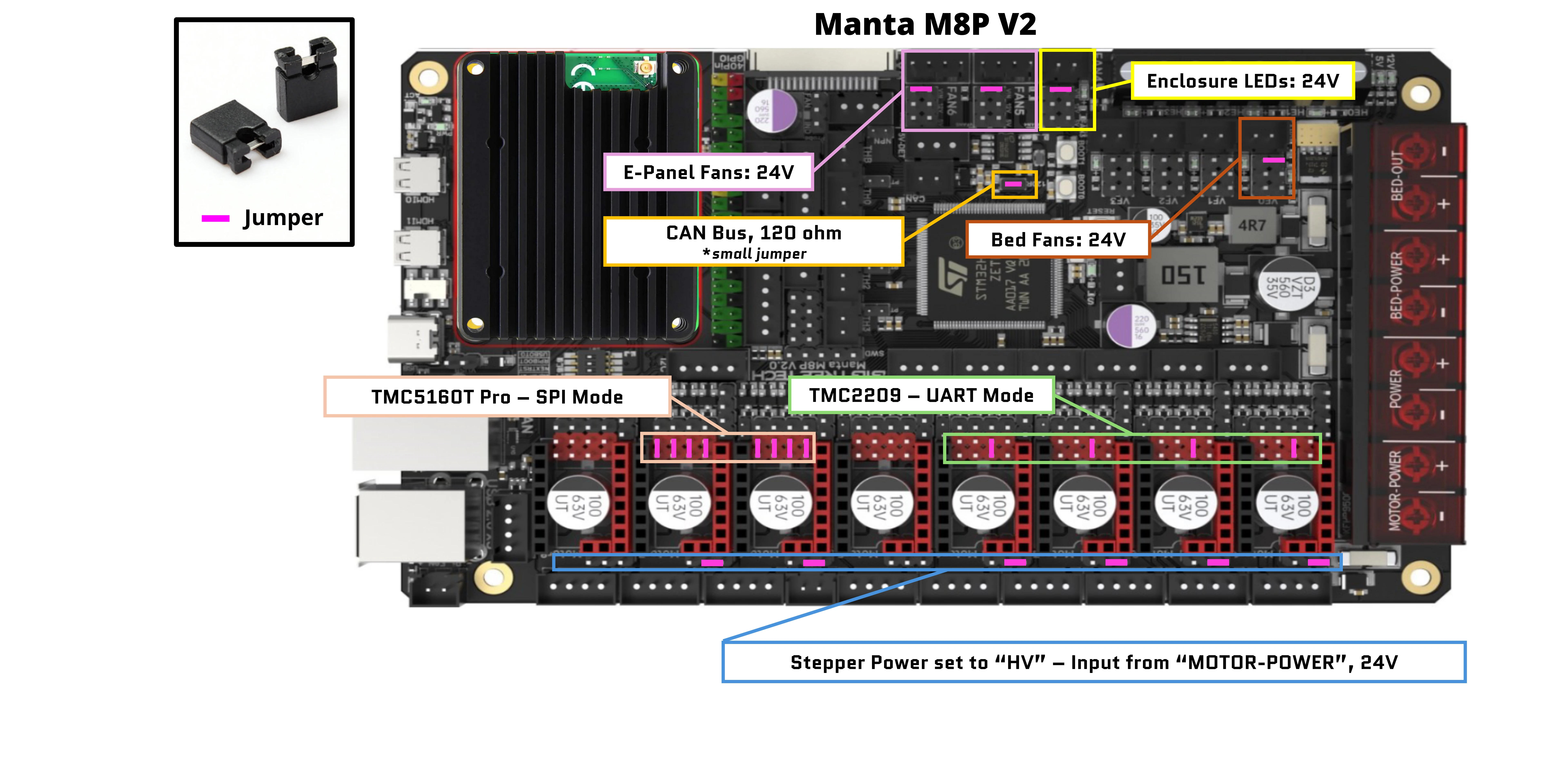
Jumpers are used to select the following settings:
- All stepper drivers are set to 24V
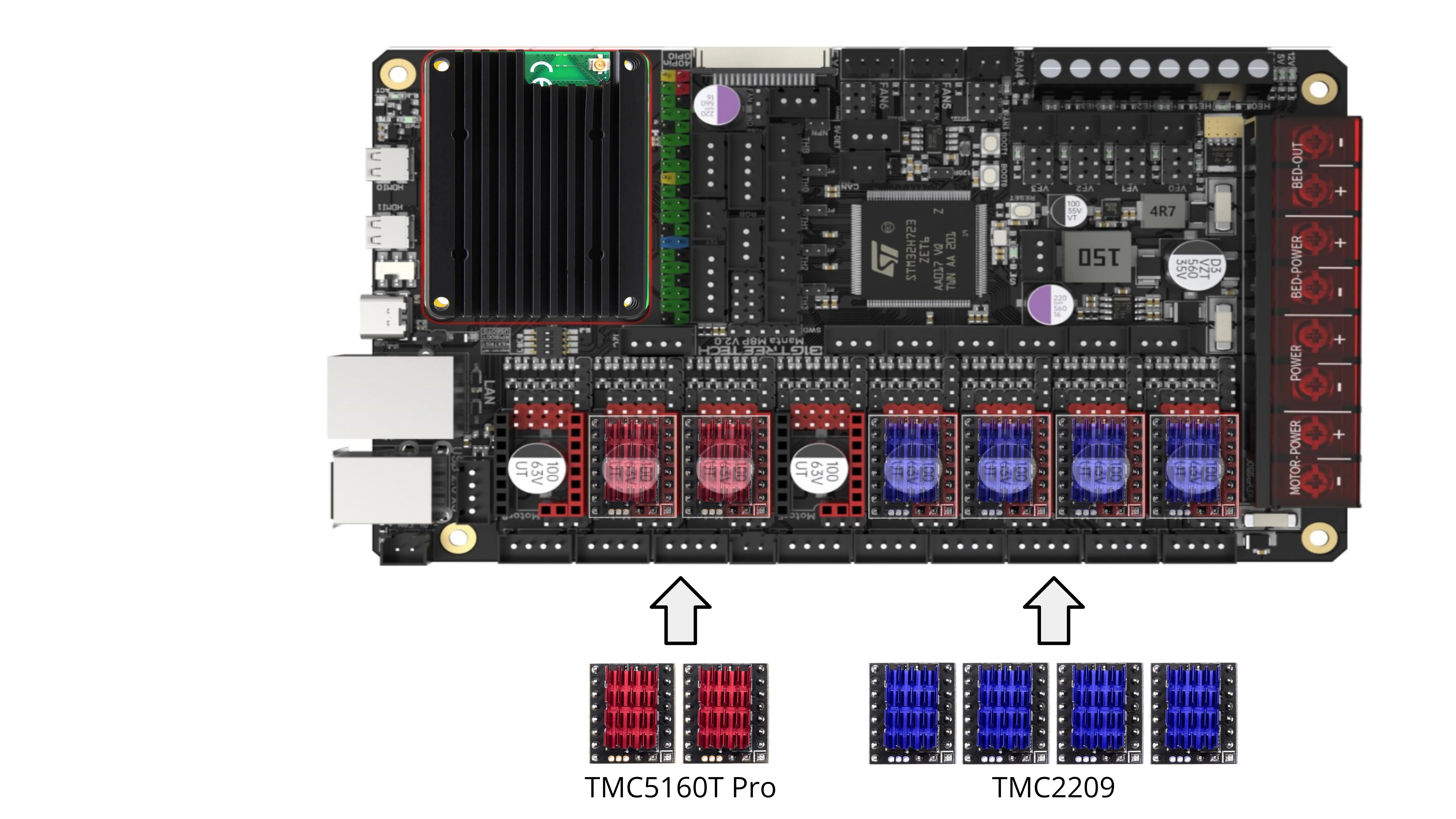
- TMC5160T Pro drivers are set to SPI mode
- TMC2209 drivers are set to UART mode
- Bed fans are set to 24V
- E-Panel fans are set to 24V
- Enclosure LEDs are set to 24V
- CAN Bus 120 ohm jumper is installed (*smaller jumper than the others)
Double-check all jumper settings before applying power — an incorrect configuration can permanently damage the board (the kind that can’t be undone). We can tell you from experience an extra or misplaced jumper makes for a good firework show.
3. Install Stepper Drivers
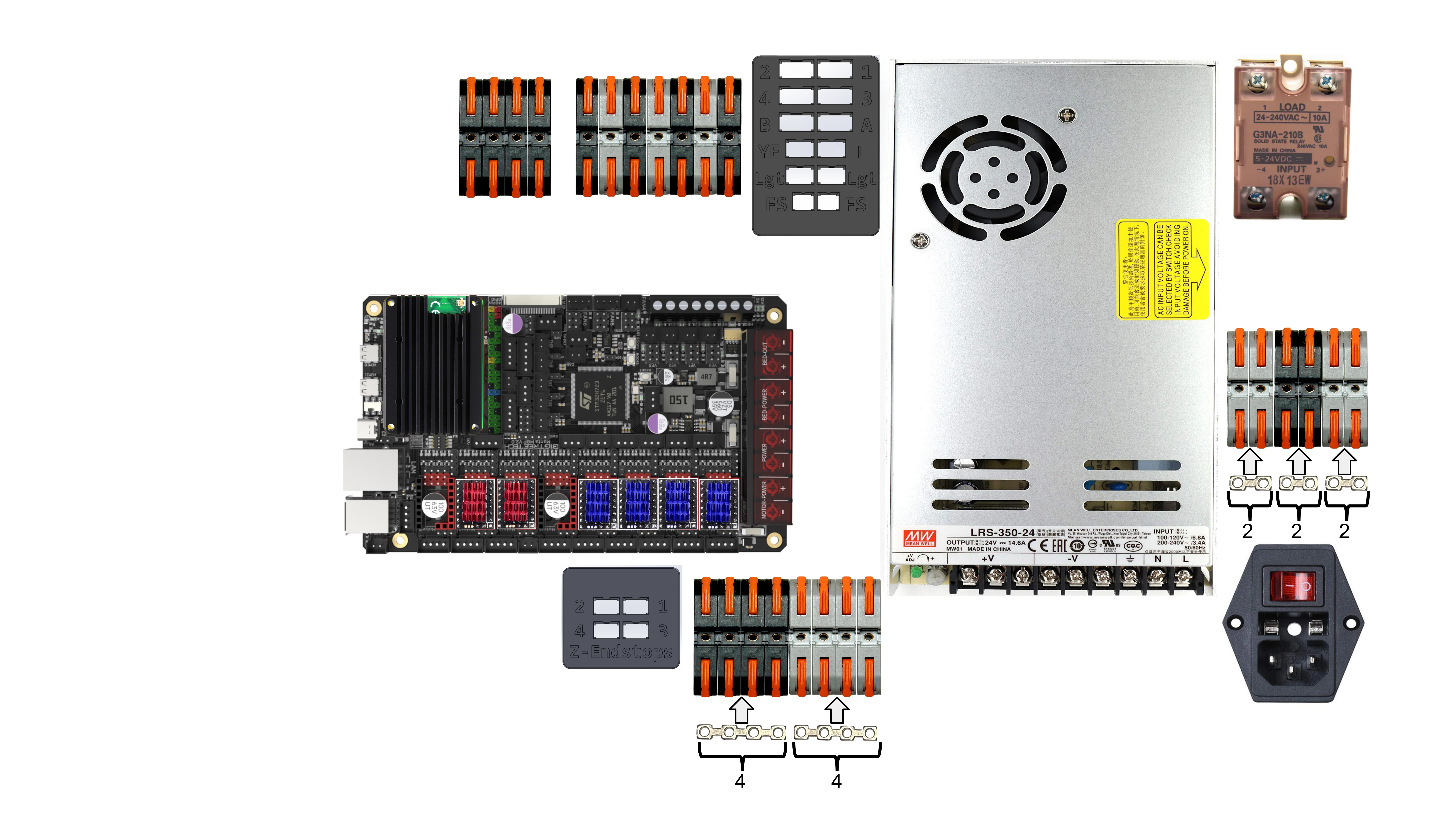
4. Install Terminal Block Bus Bars
- Cut terminal block bus bars to length
- Trim excess material from where the cut was made
- Install bus bars in terminal blocks as shown
Double-check that each bus bar is cut to the correct node length. Trim any excess material between bus bars so they are not close to touching. When finished, it should match the image above.

5. Install Terminal Block Bus Bar Fasteners
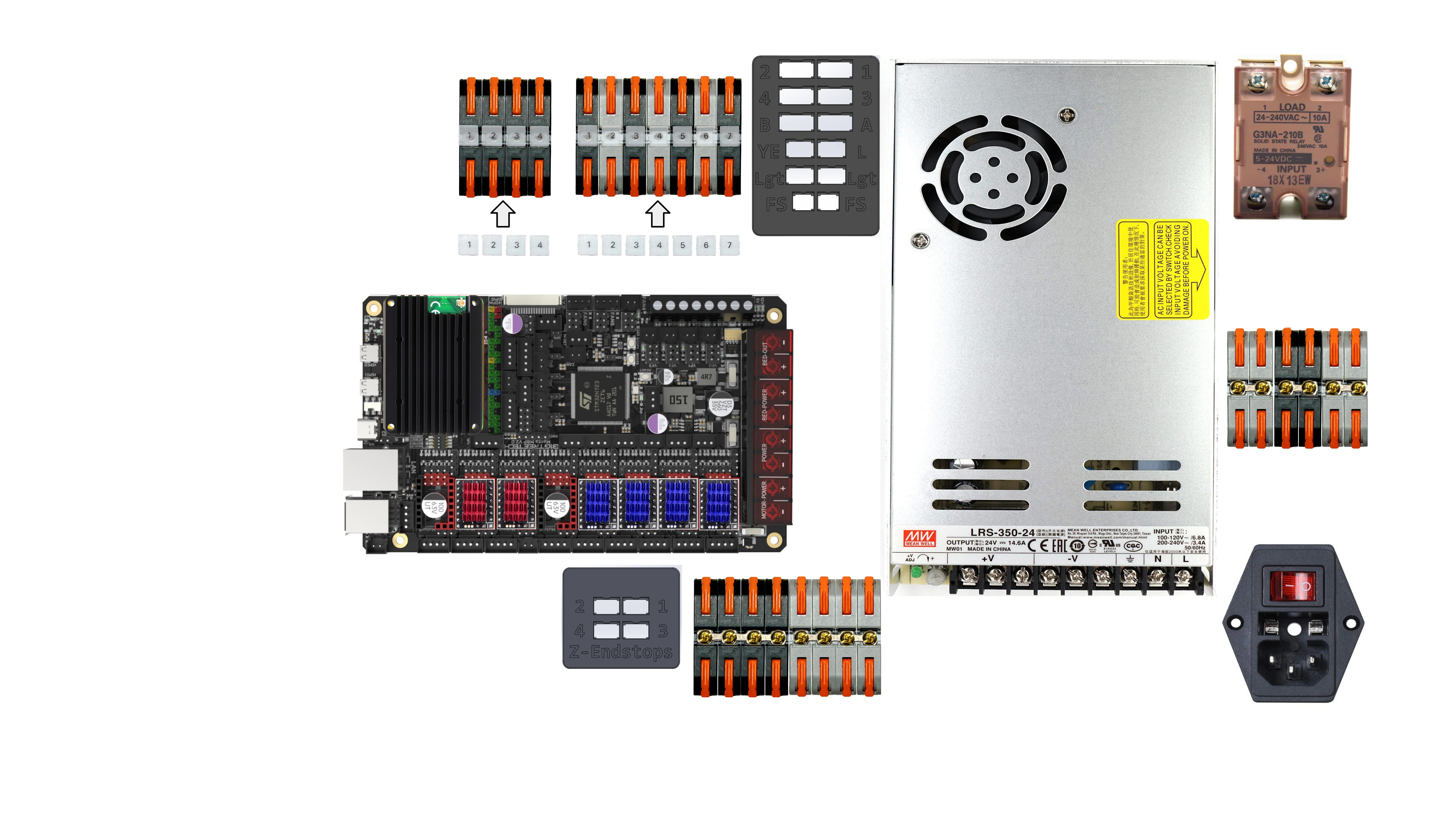
6. Install Terminal Block Number Covers
- Install terminal block number covers for Terminal Block CAN (TBCAN) and Terminal Block Bed (TBB)
- We will leave the others uncovered for the next steps
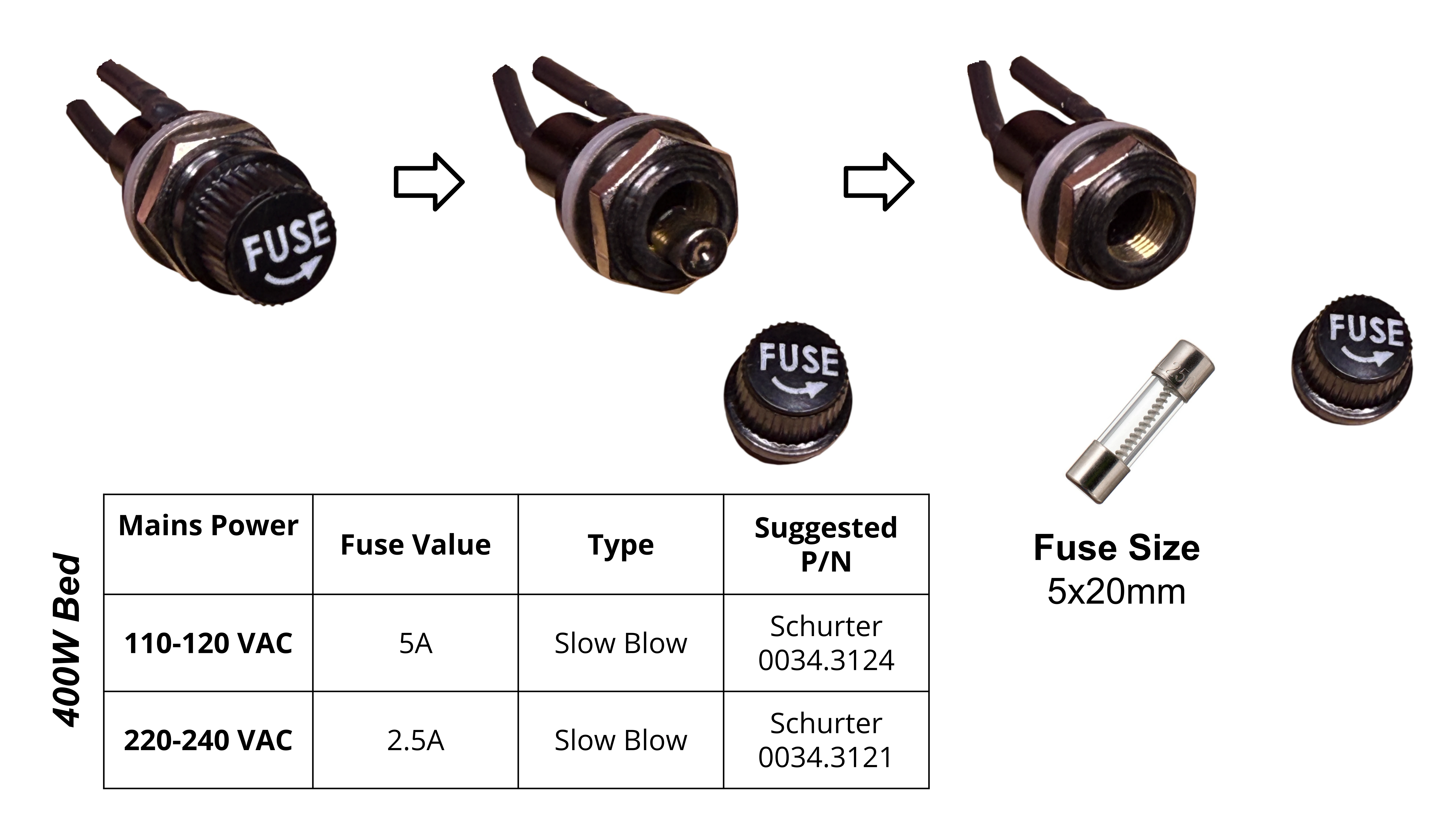
7. Check Fuse Amperage - IEC C14 Plug
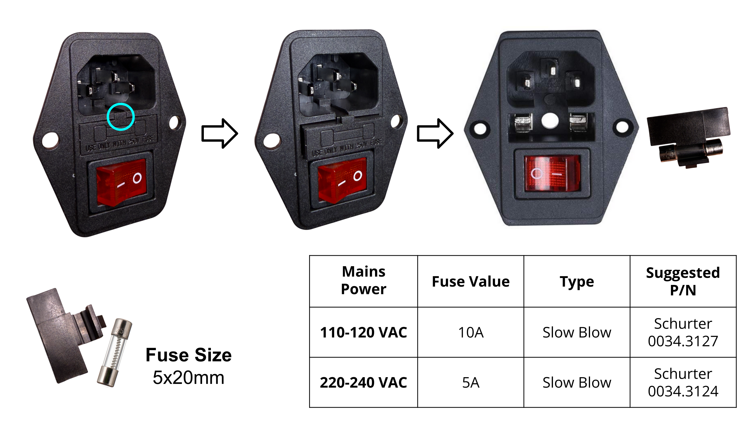
- This step is a safety check to make sure the components have the correct fuse sizes for your region.
- Remove the fuse and verify that the amperage rating matches the value listed in the table.
- Re-install the fuse
Do not assume the installed fuses are correct. An oversized fuse may not blow when a fault occurs, which can allow wires or components to overheat. This can damage the printer, create a fire hazard, or cause serious injury. Always verify the fuse size before applying power.
8. Check Fuse Amperage - Bed Fuse (Z-07)
- This step is a safety check to make sure the components have the correct fuse sizes for your region.
- Remove the fuse and verify that the amperage rating matches the value listed in the table.
- Re-install the fuse
Do not assume the installed fuses are correct. An oversized fuse may not blow when a fault occurs, which can allow wires or components to overheat. This can damage the printer, create a fire hazard, or cause serious injury. Always verify the fuse size before applying power.
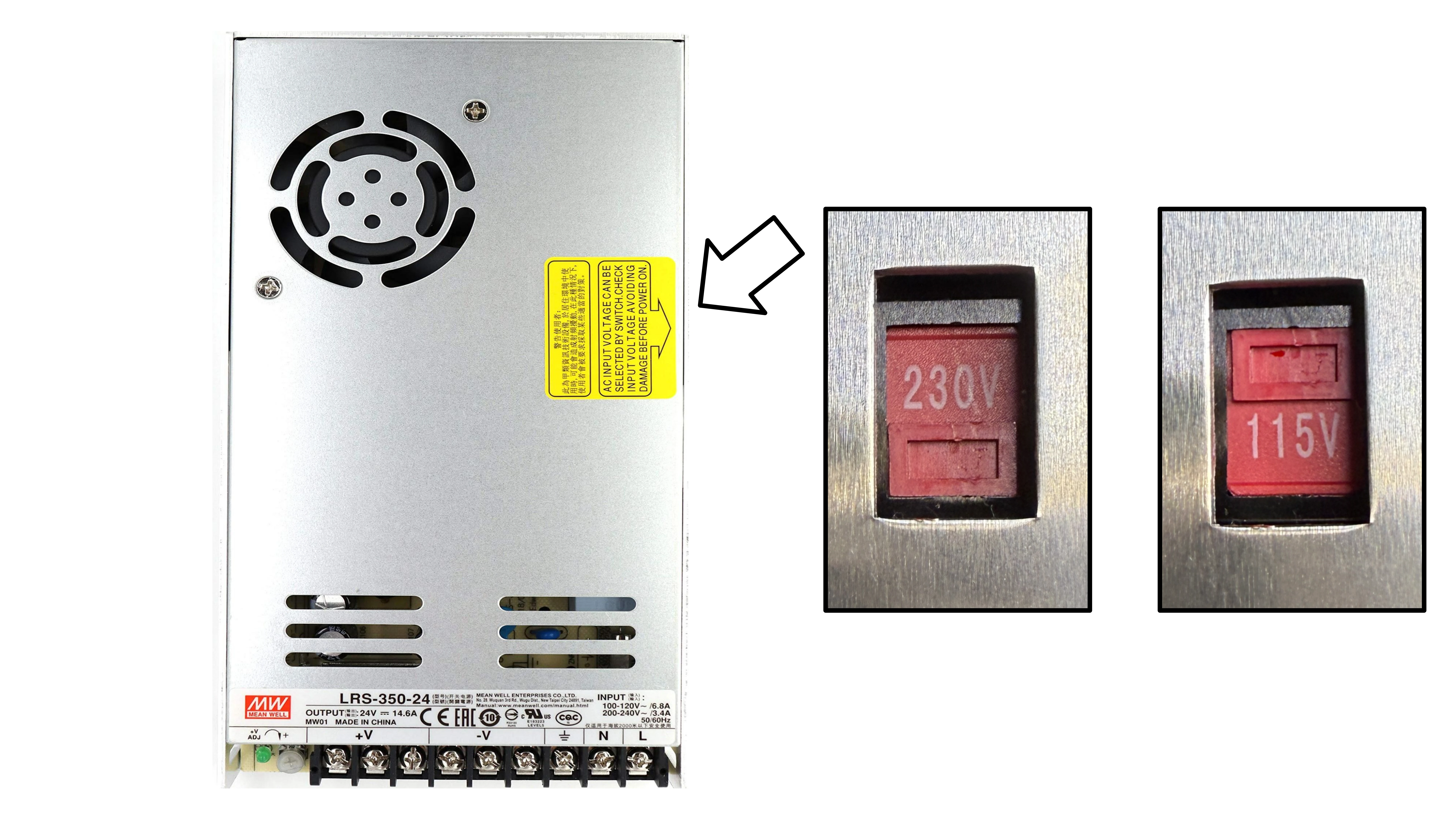
9. Check PSU’s AC Input Voltage Switch
- This step is a safety check to make sure the PSU is set to accept the mains power for your region.
- Locate the switch on the side of the PSU
- Ensure it is set to the AC input voltage for your region.
Do not assume the PSU’s AC input voltage switch is set correctly. An incorrectly set switch can damage the printer, create a fire hazard, or cause serious injury. Always verify the PSU’s AC input voltage switch setting before applying power.
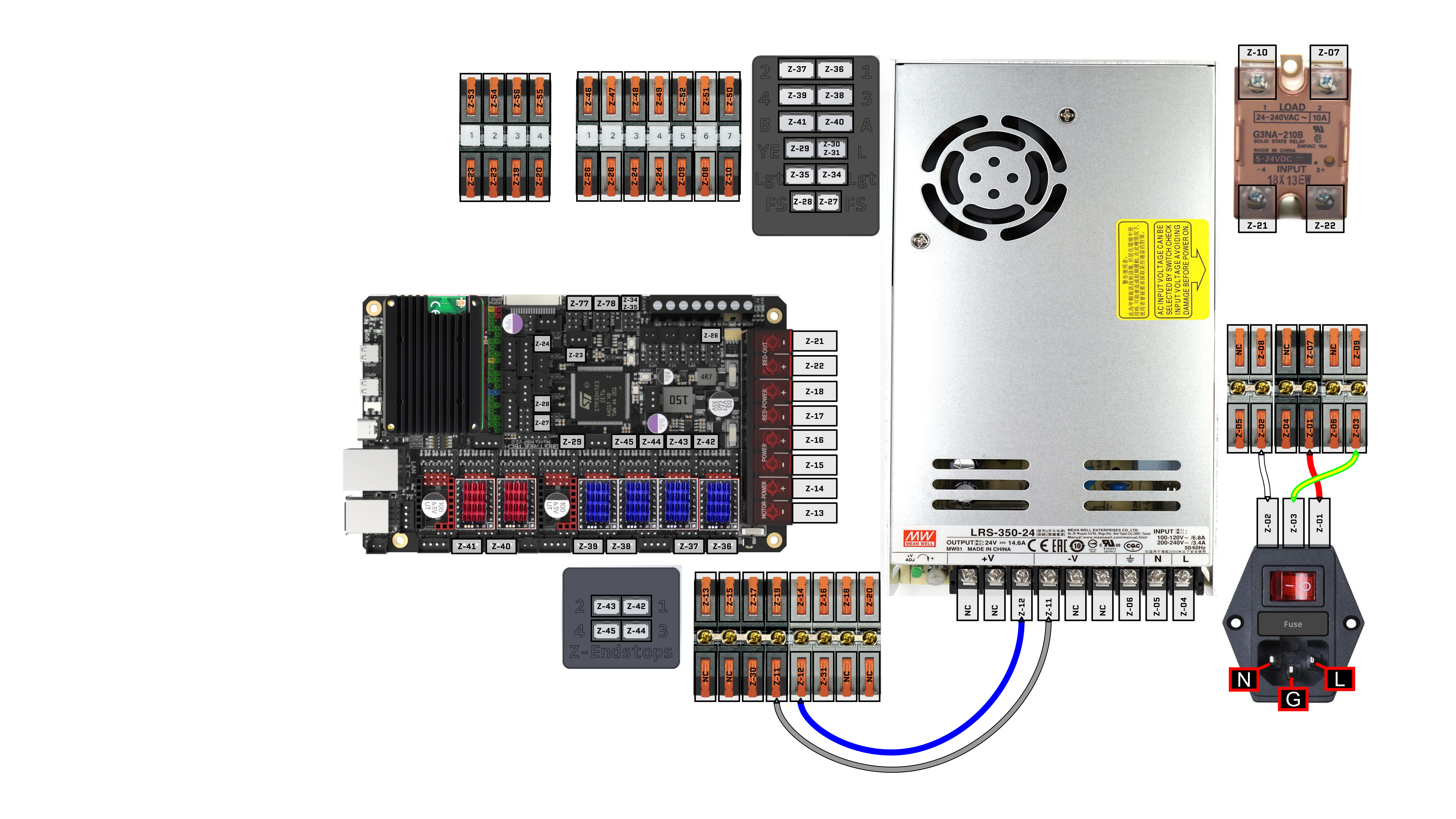
10. Install Cables: Z-01, Z-02, Z-03, Z-11, Z-12
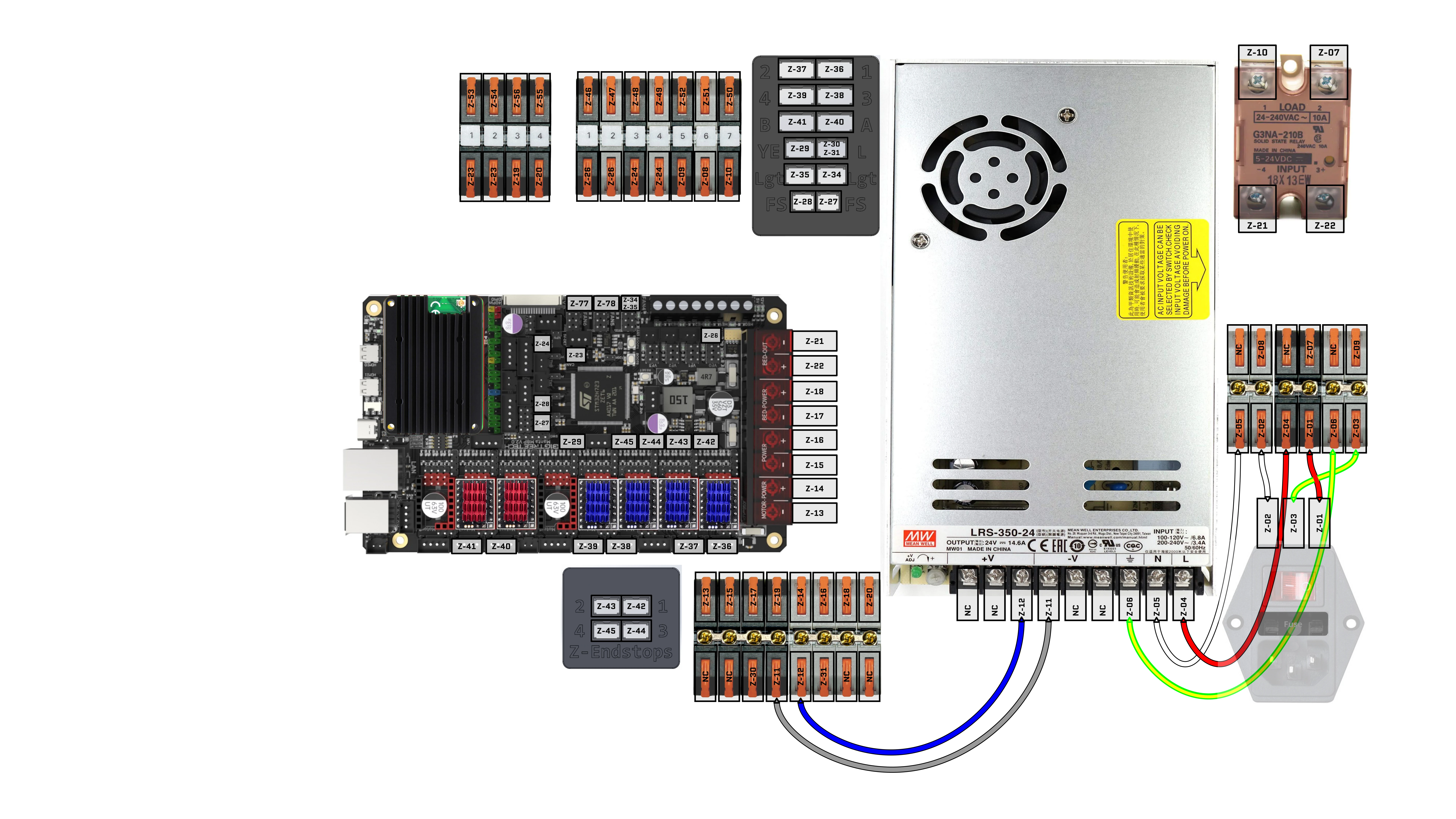
11. Install Cables: Z-04, Z-05, Z-06
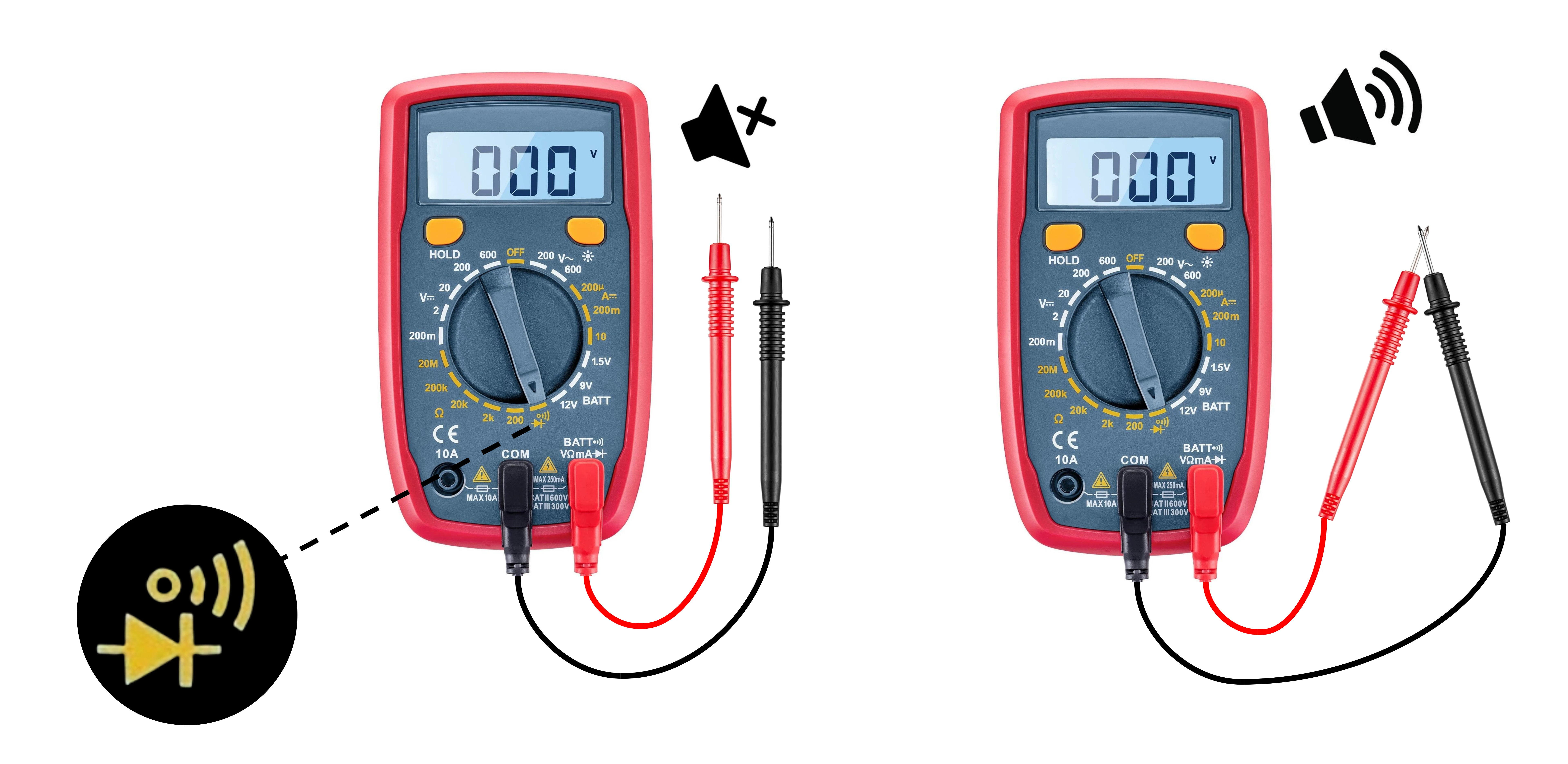
12. Prepare Multimeter for Continuity Checks
- Set multimeter to continuity mode
- Touch the multimeter leads together - The multimeter should beep
Always test the continuity mode is reporting accurately by touching the two multimeter leads together - This should result in a beeping noise.
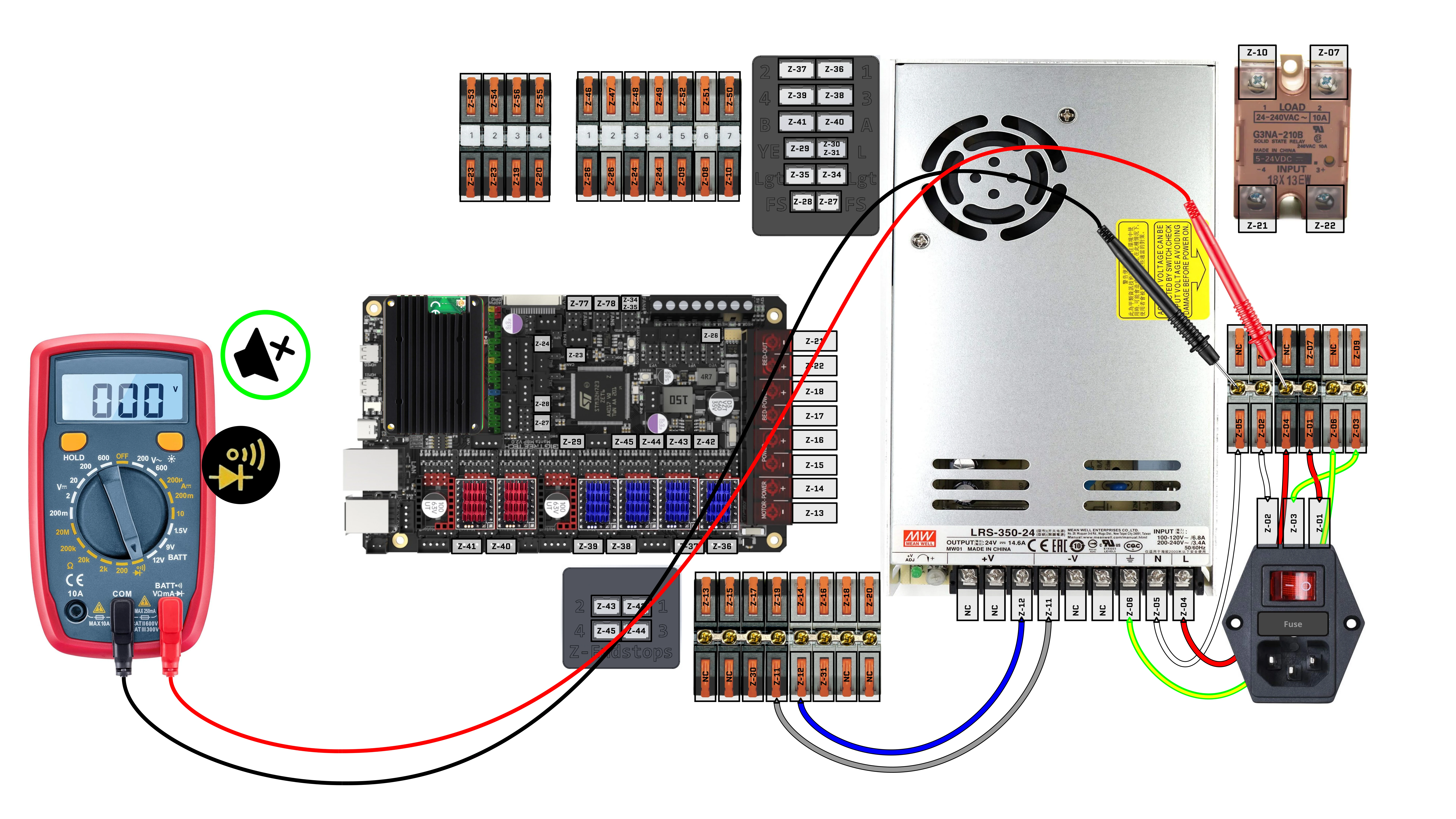
13. Check for short between AC Live (L) and AC Neutral (N)
Preprequisite:
- Power is disconnected
- Set multimeter to continuity mode
- Multimeter continuity mode tested and working (beeps when touching leads)
Test:
- Touch other lead to AC Live (L) bus bar
- Touch one lead to AC Neutral (N) bus bar
Pass: No Sound
Fail: Multimeter Beeps
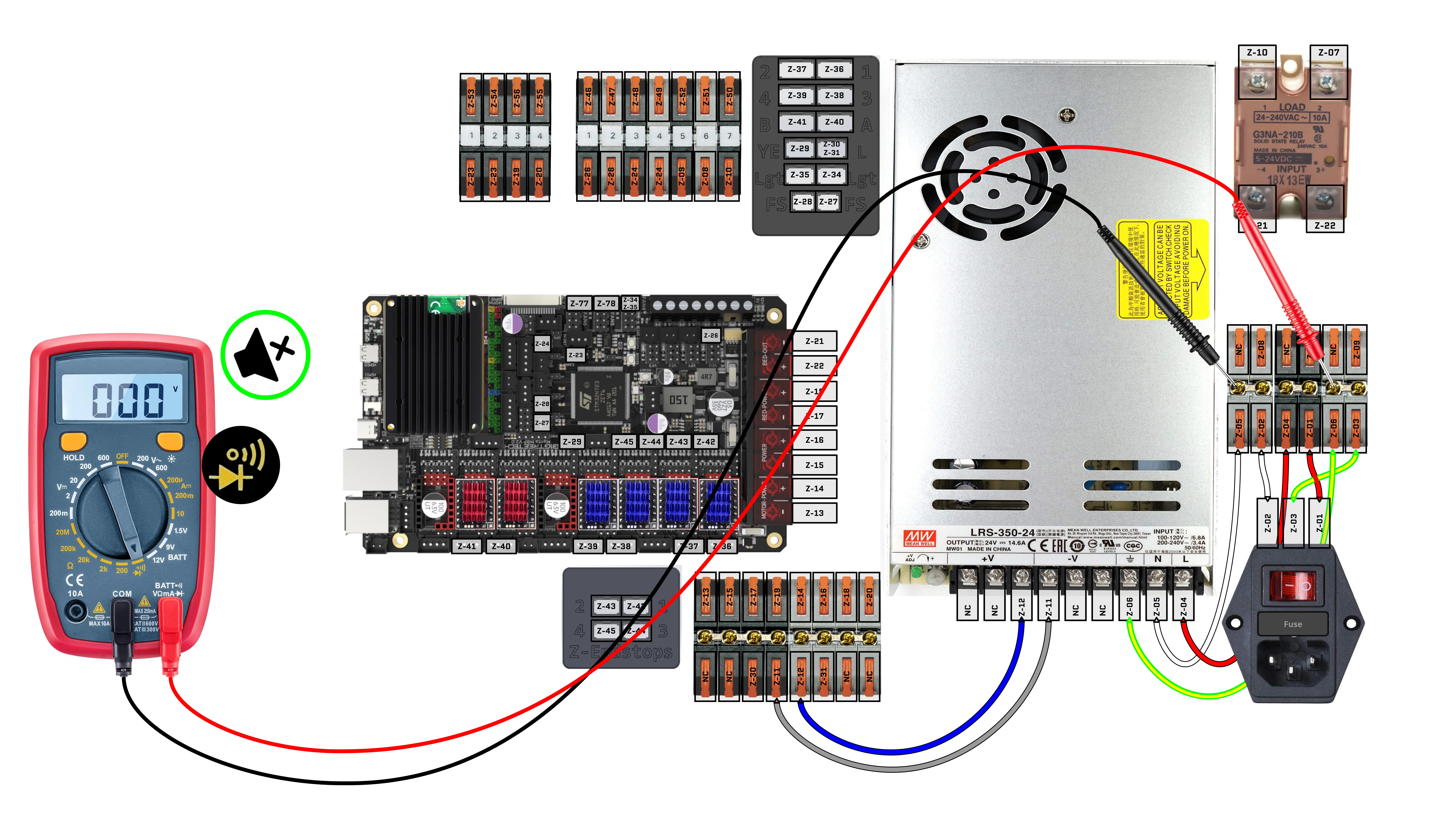
14. Check for short between AC Neutral (N) and AC Earth (⏚)
Preprequisite:
- Power is disconnected
- Set multimeter to continuity mode
- Multimeter continuity mode tested and working (beeps when touching leads)
Test:
- Touch one lead to AC Neutral (N) bus bar
- Touch other lead to AC Earth (⏚) bus bar
Pass: No Sound
Fail: Multimeter Beeps
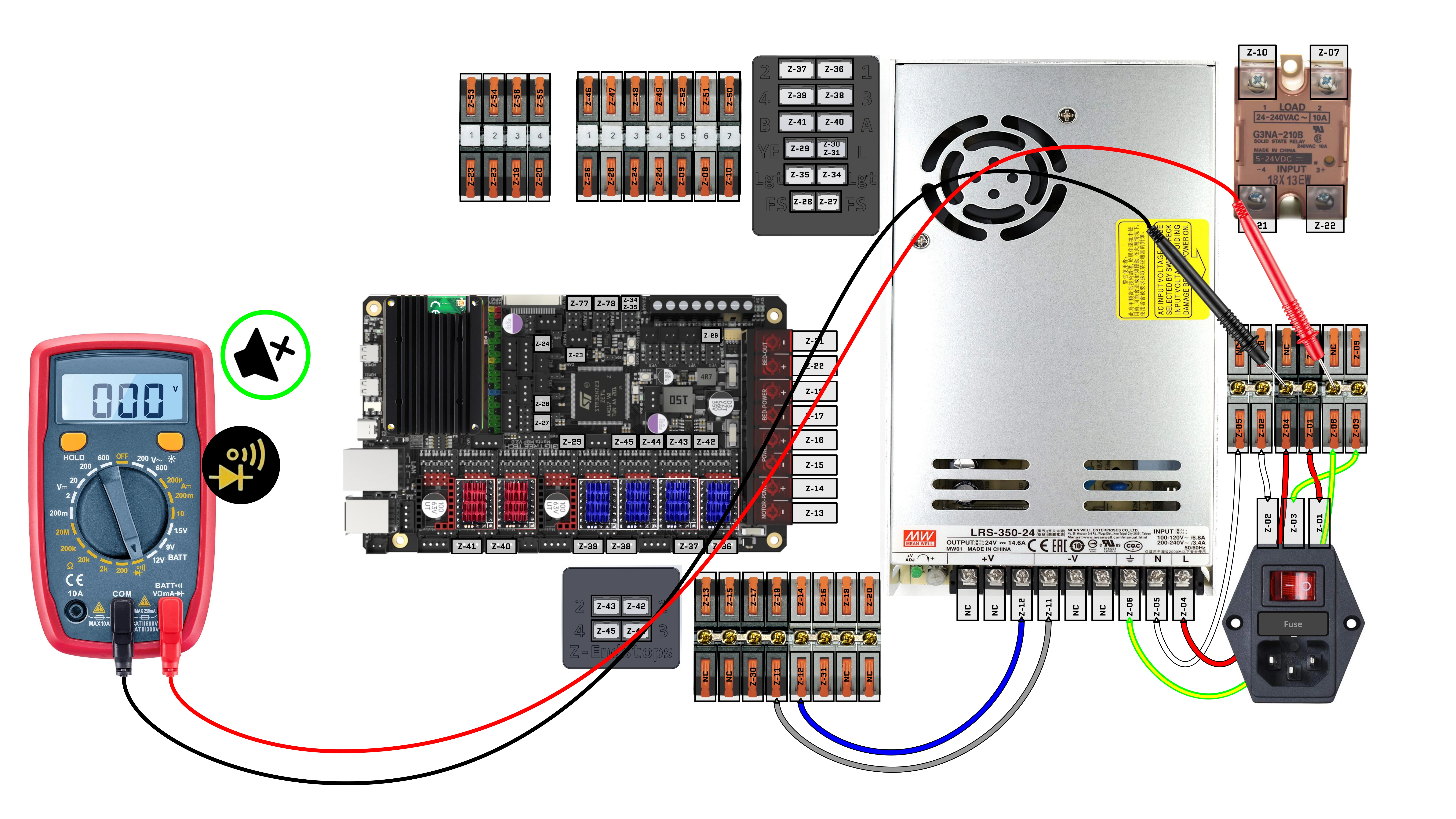
15. Check for short between AC Live (L) and AC Earth (⏚)
Preprequisite:
- Power is disconnected
- Set multimeter to continuity mode
- Multimeter continuity mode tested and working (beeps when touching leads)
Test:
- Touch one lead to AC Live (L) bus bar
- Touch other lead to AC Earth (⏚) bus bar
Pass: No Sound
Fail: Multimeter Beeps
16. Check for short between PSU’s DC(+) and DC(-)
Preprequisite:
- Power is disconnected
- Set multimeter to continuity mode
- Multimeter continuity mode tested and working (beeps when touching leads)
Test:
- Touch one lead to DC(+) bus bar
- Touch other lead to DC(-) bus bar
Pass: No Sound
Fail: Multimeter Beeps
17. Check for continuity between IEC C14 plug and PSU for AC Live (L)
Preprequisite:
- Power is disconnected
- Set multimeter to continuity mode
- Multimeter continuity mode tested and working (beeps when touching leads)
Test:
- Touch one lead to IEC C14 Plug’s (L) pin
- Touch other lead to PSU’s AC (L) input
Pass: Multimeter Beeps
Fail: No Sound
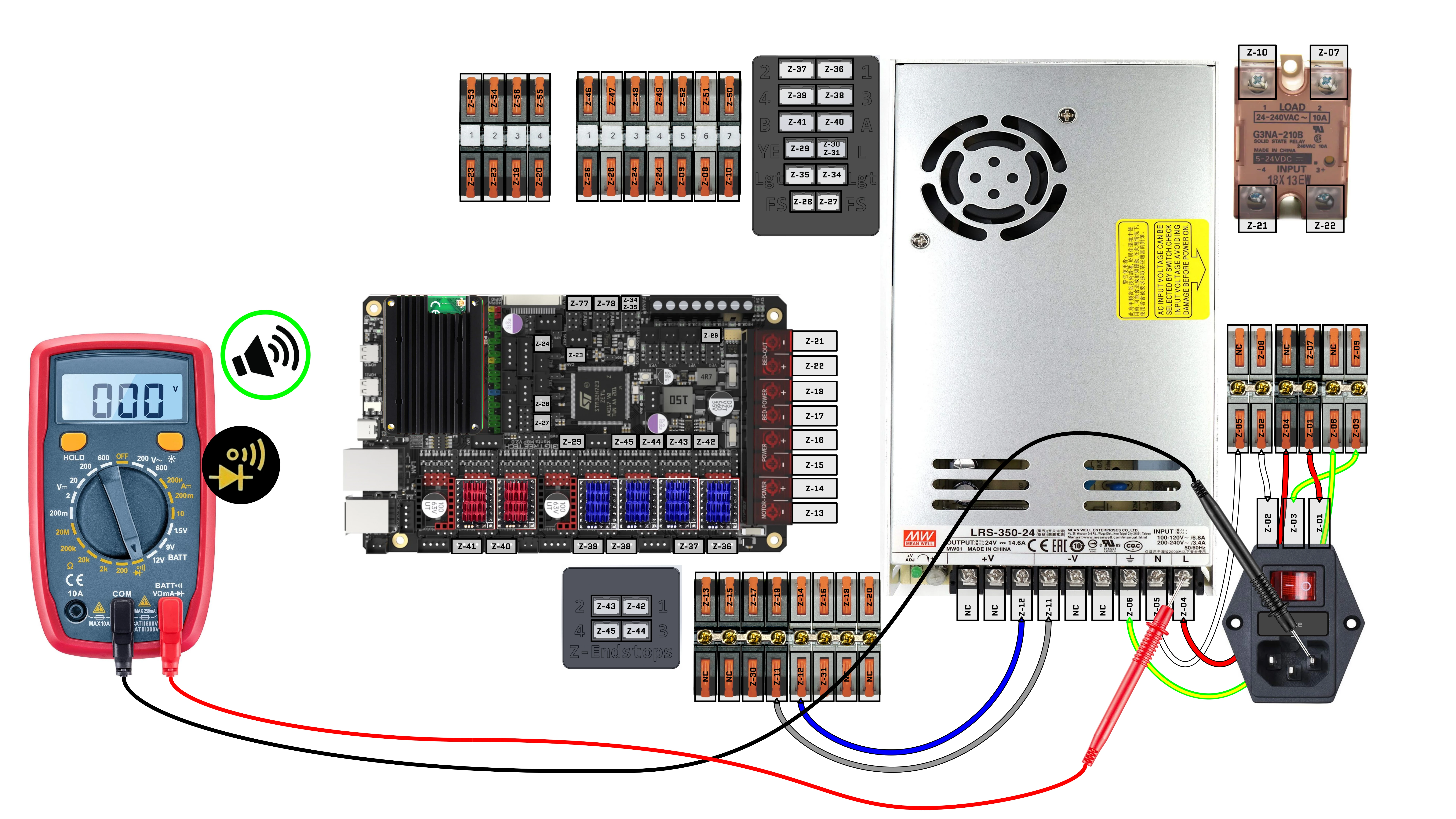
18. Check for continuity between IEC C14 plug and PSU for AC Neutral (N)
Preprequisite:
- Power is disconnected
- Set multimeter to continuity mode
- Multimeter continuity mode tested and working (beeps when touching leads)
Test:
- Touch one lead to IEC C14 Plug’s (N) pin
- Touch other lead to PSU’s AC (N) input
Pass: Multimeter Beeps
Fail: No Sound
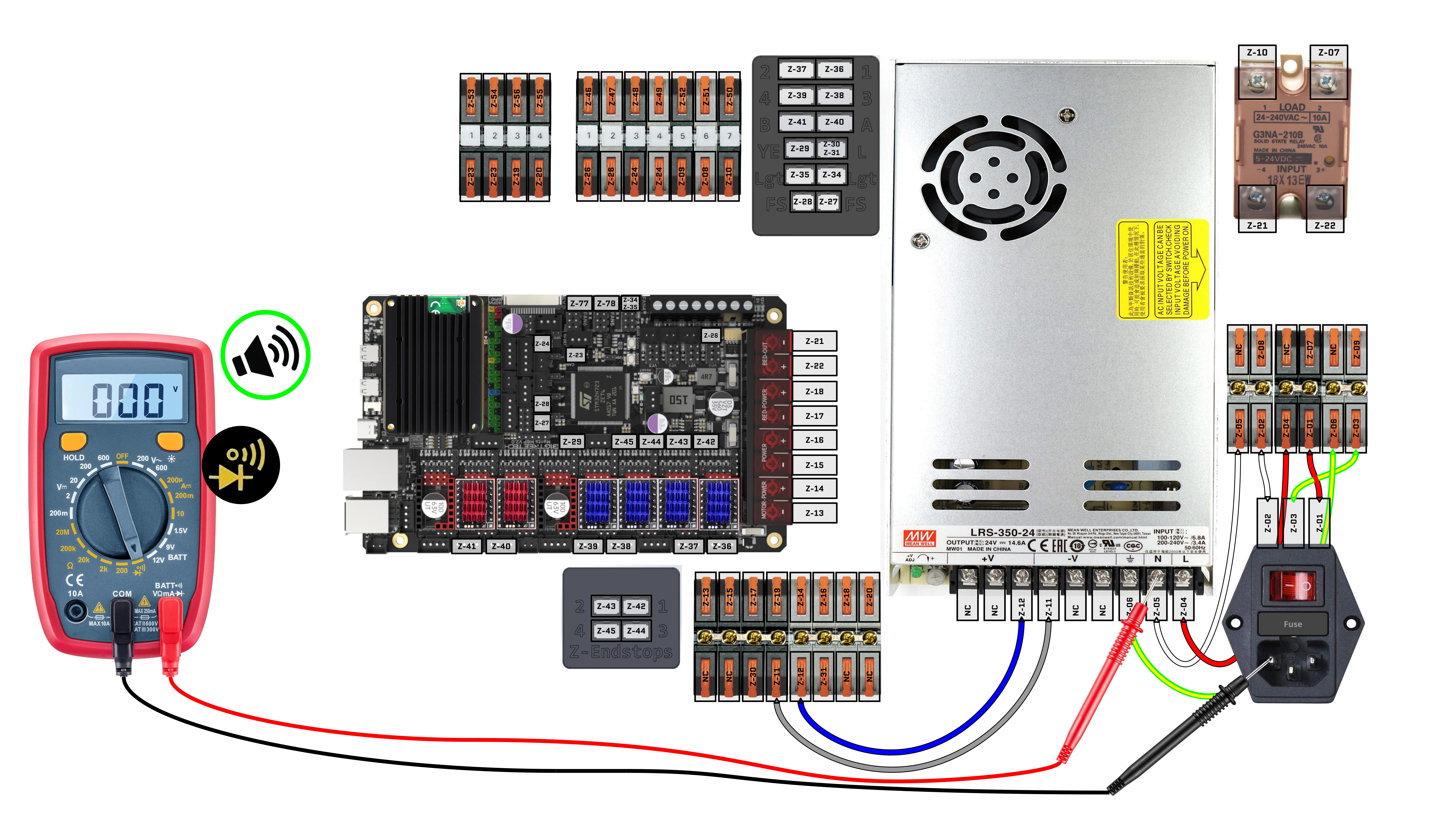
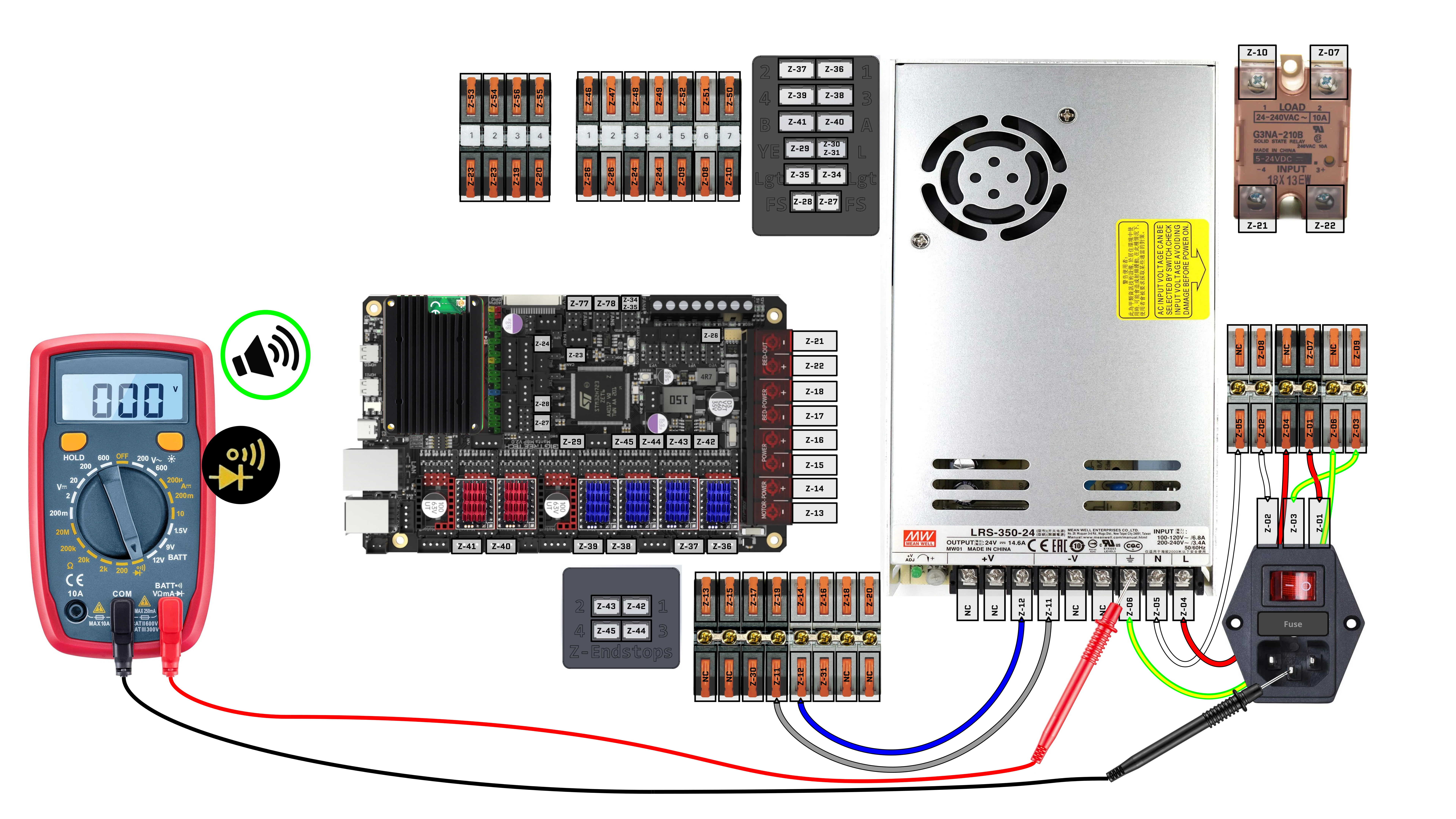
19. Check for continuity between IEC C14 plug and PSU for AC Earth (⏚)
Preprequisite:
- Power is disconnected
- Set multimeter to continuity mode
- Multimeter continuity mode tested and working (beeps when touching leads)
Test:
- Touch one lead to IEC C14 Plug’s (⏚) pin
- Touch other lead to PSU’s AC (⏚) input
Pass: Multimeter Beeps
Fail: No Sound
20. Preparing for First Power ON
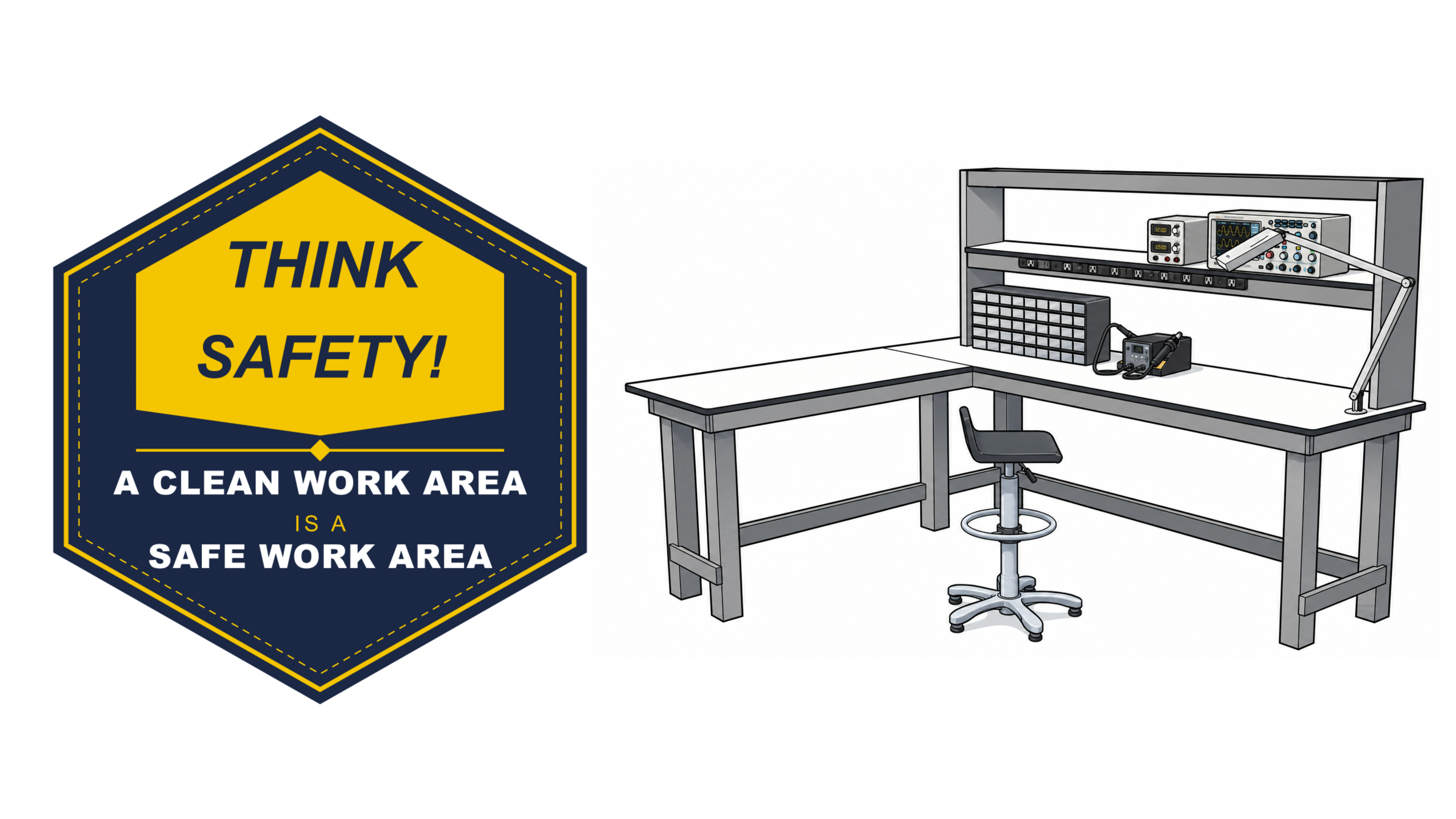
Don’t wire electronics in a cluttered area, as it greatly increases the risk of accidentally shorting something.
Always prioritize your safety and the safety of those around you
- Wear safety glasses, and make sure anyone observing nearby does the same.
- Anyone working close enough to accidentally contact electrical components should wear insulating gloves.
- Be prepared. The odds may be low, but they are not zero. Keep a fire extinguisher nearby in case of faulty components or a wiring mistake.

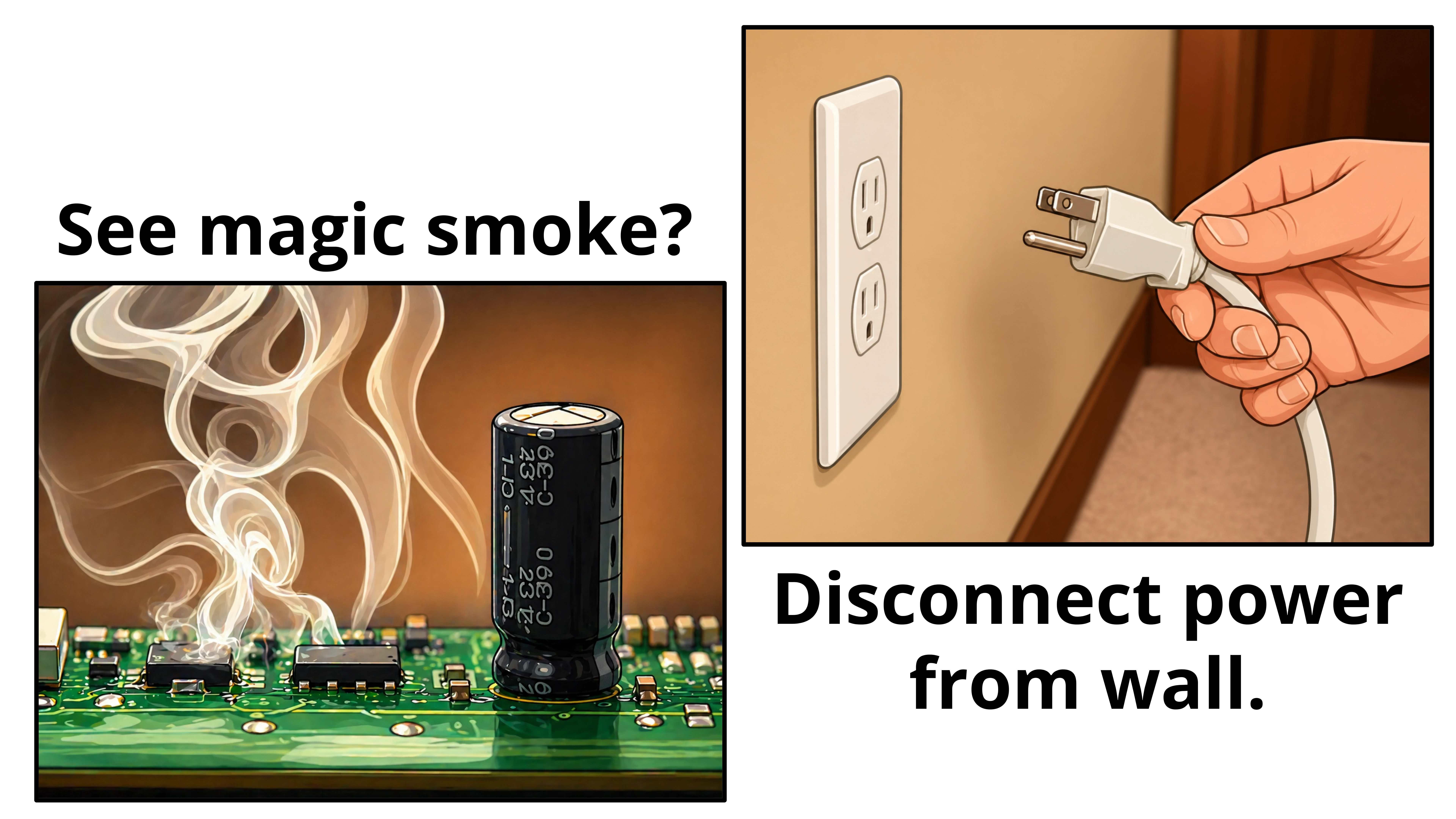
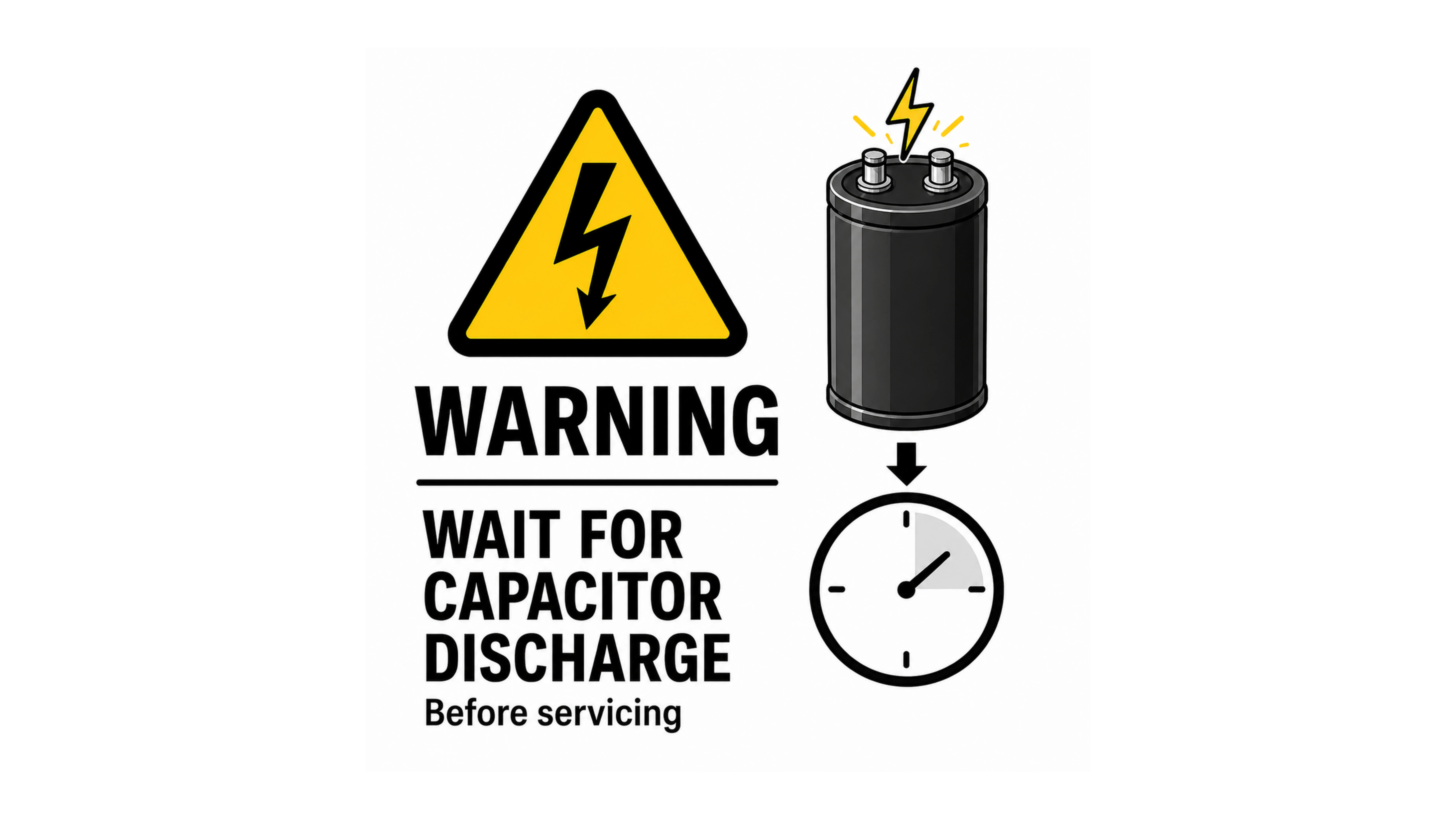
In the following steps, the power supply unit (PSU) will be turned on. After the PSU is turned off, wait several minutes before handling any electronics to allow the capacitors to fully discharge.
21. Adjusting PSU to 24V
Now that you are working safe and responsibly, lets get on with it!
Prerequisite: Power is disconnected, jumpers installed, PSU power switch checked, fuses checked, continuity checks all passed
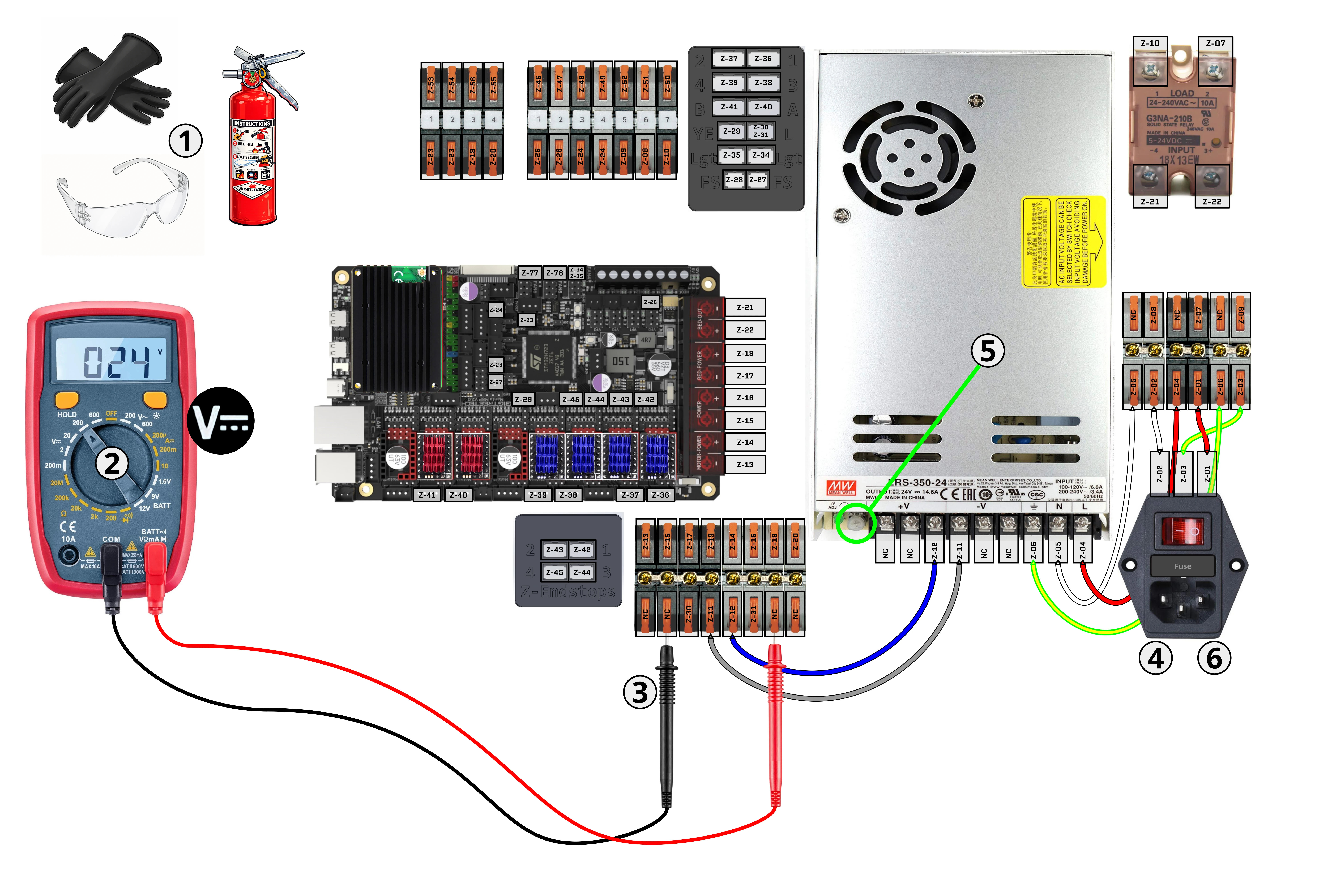
- Safety First: Ensure you and others around you observing are wearing the appropriate PPE. Also have your safety equipment on hand.
- Set voltmeter to DC Voltage Mode, choosing the lowest limit that is >=24V. In our image, that number is 200.
- Connect the voltmeter’s leads to the corresponding polarity terminals on the 24V lift lever terminal block: red lead to V+ and black lead to V−.
- Connect power cable, hold on to your butts, and power ON. A LED should light up on 24V PSU. Voltmeter should now have a reading close to 24V.
- Adjust the potentiometer on the 24V PSU until voltmeter reads 24V.
- Power OFF and disconnect the power cable. Remove the voltmeter from the 24V terminal block.
22. Install Terminal Block Covers
- Install terminal block covers for Terminal Block AC Power (TBAC) and Terminal Block DC Power (TBDC)
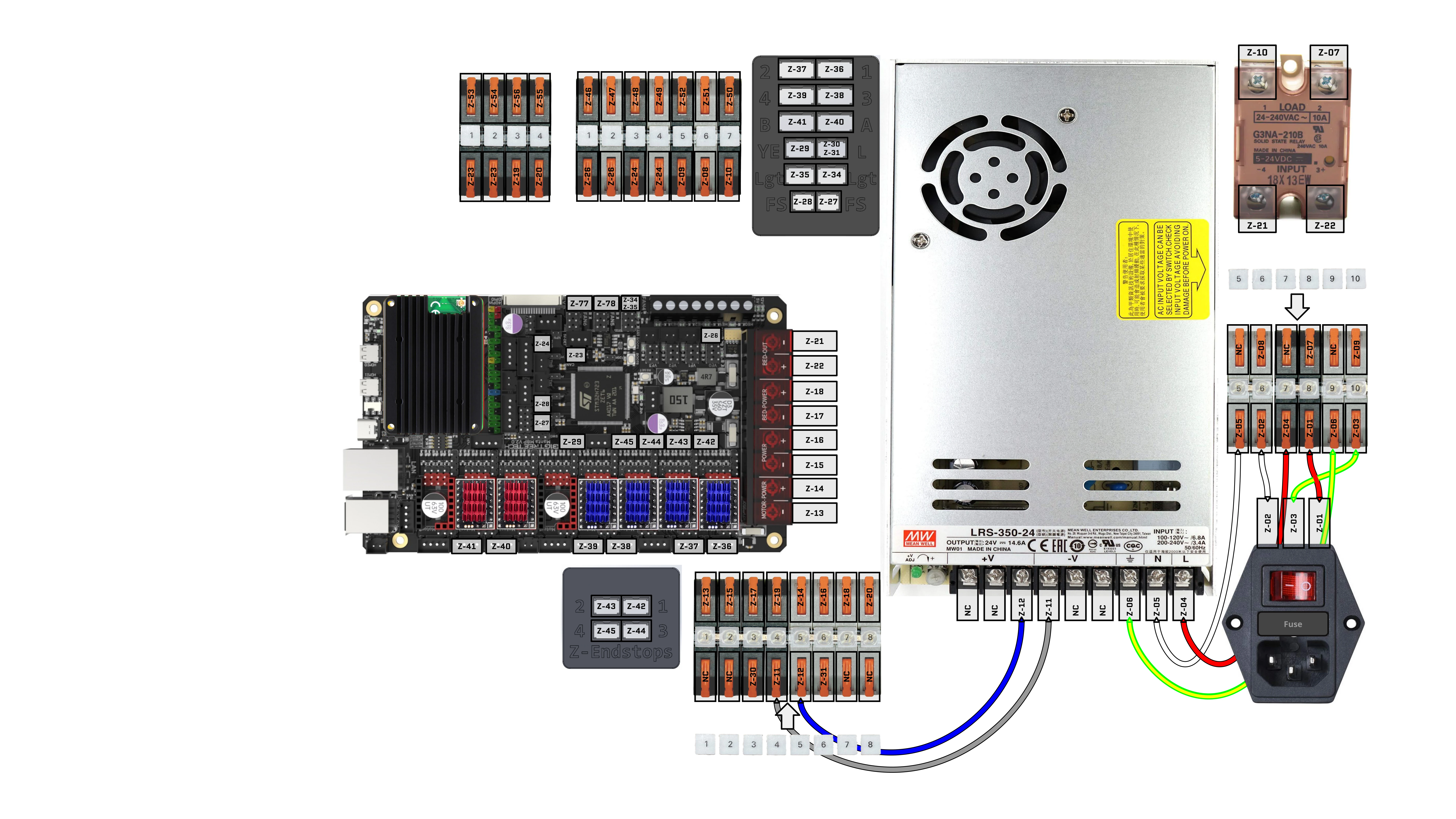
23. Install Cables: Z-13, Z-15, Z-17, Z-19
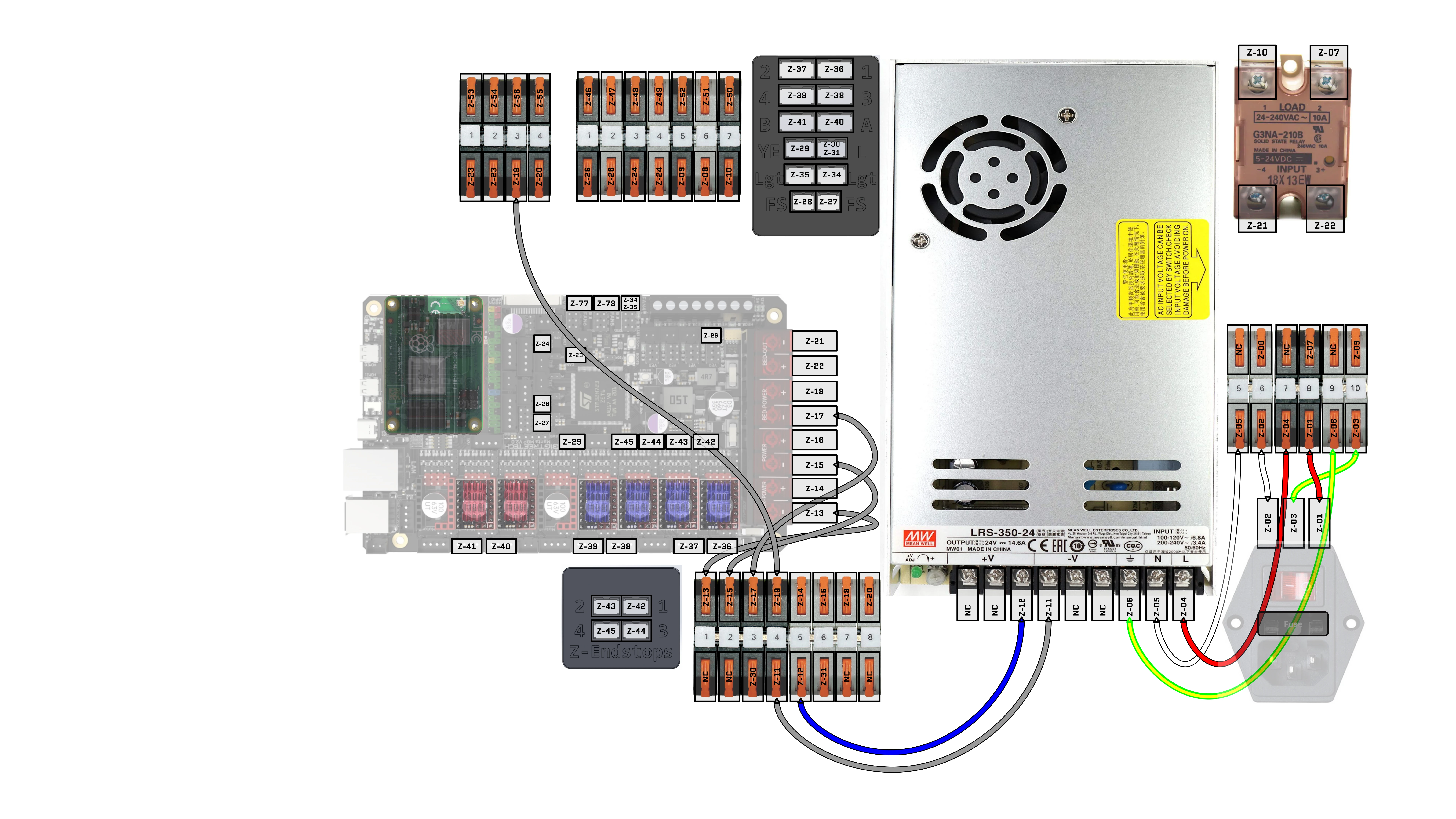
24. Install Cables: Z-14, Z-16, Z-18, Z-20
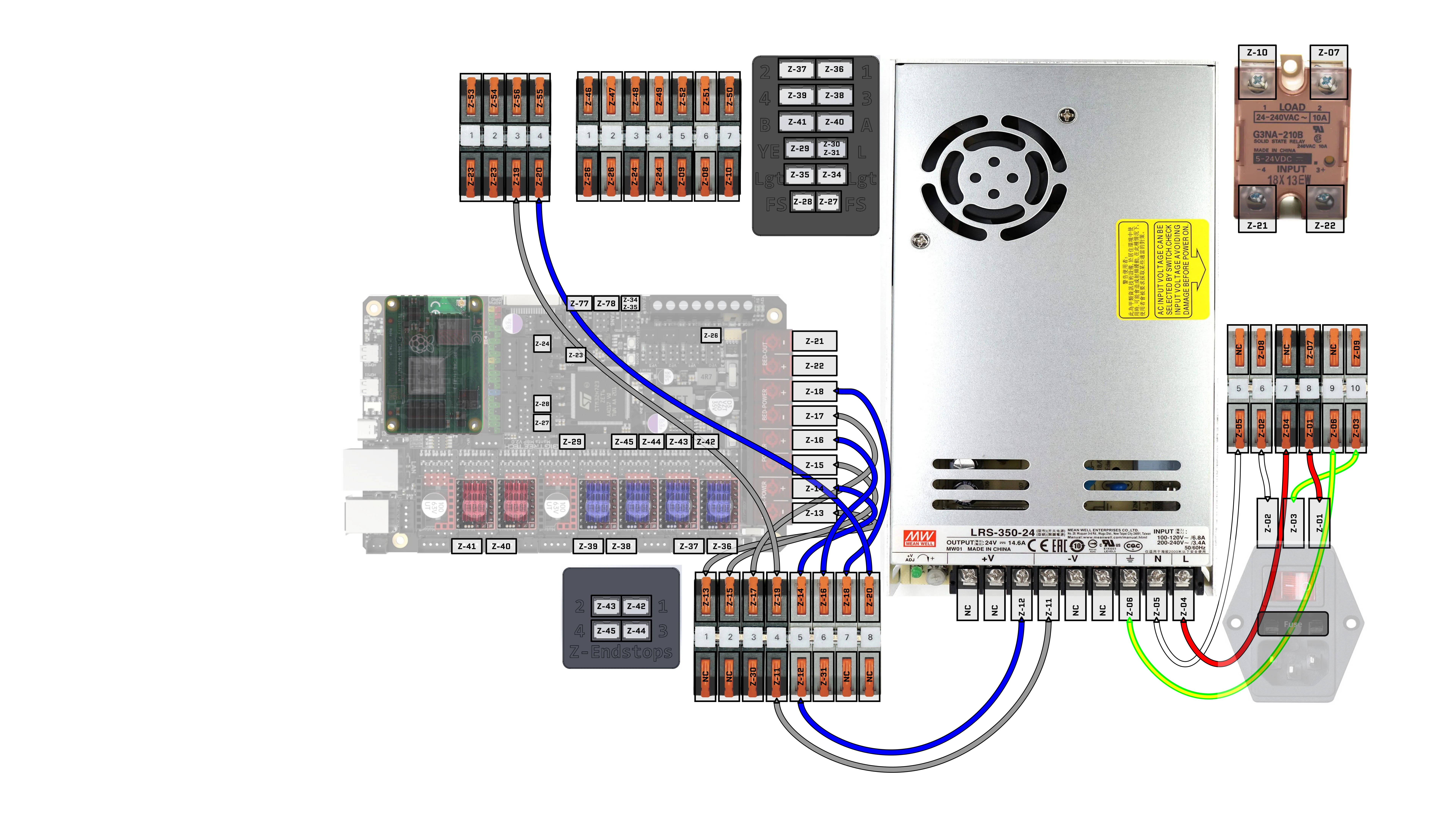
25. Install Cables: Z-07, Z-08, Z-09, Z-10, Z-21, Z-22
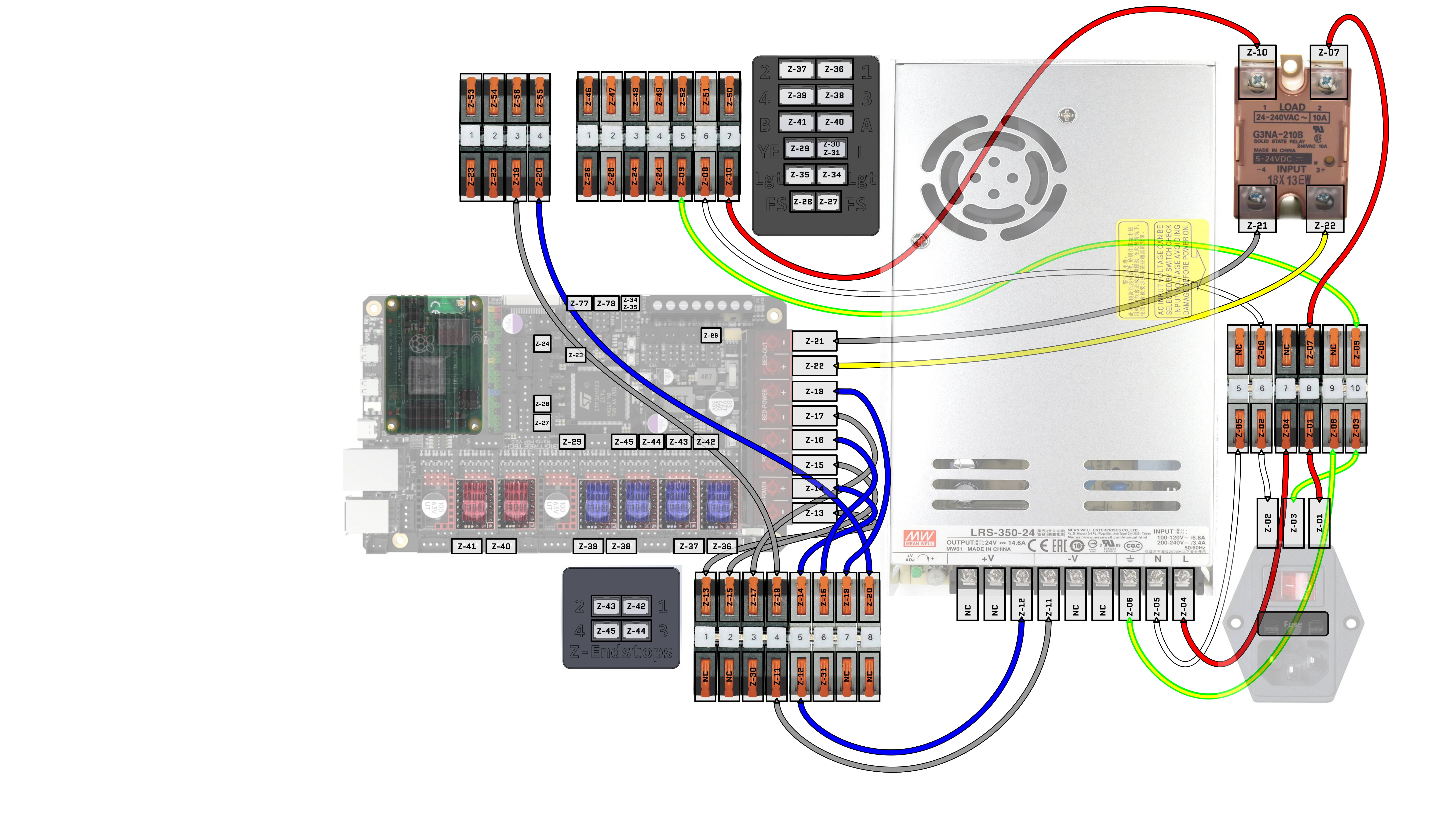
26. Install Cables: Z-23, Z-24, Z-26
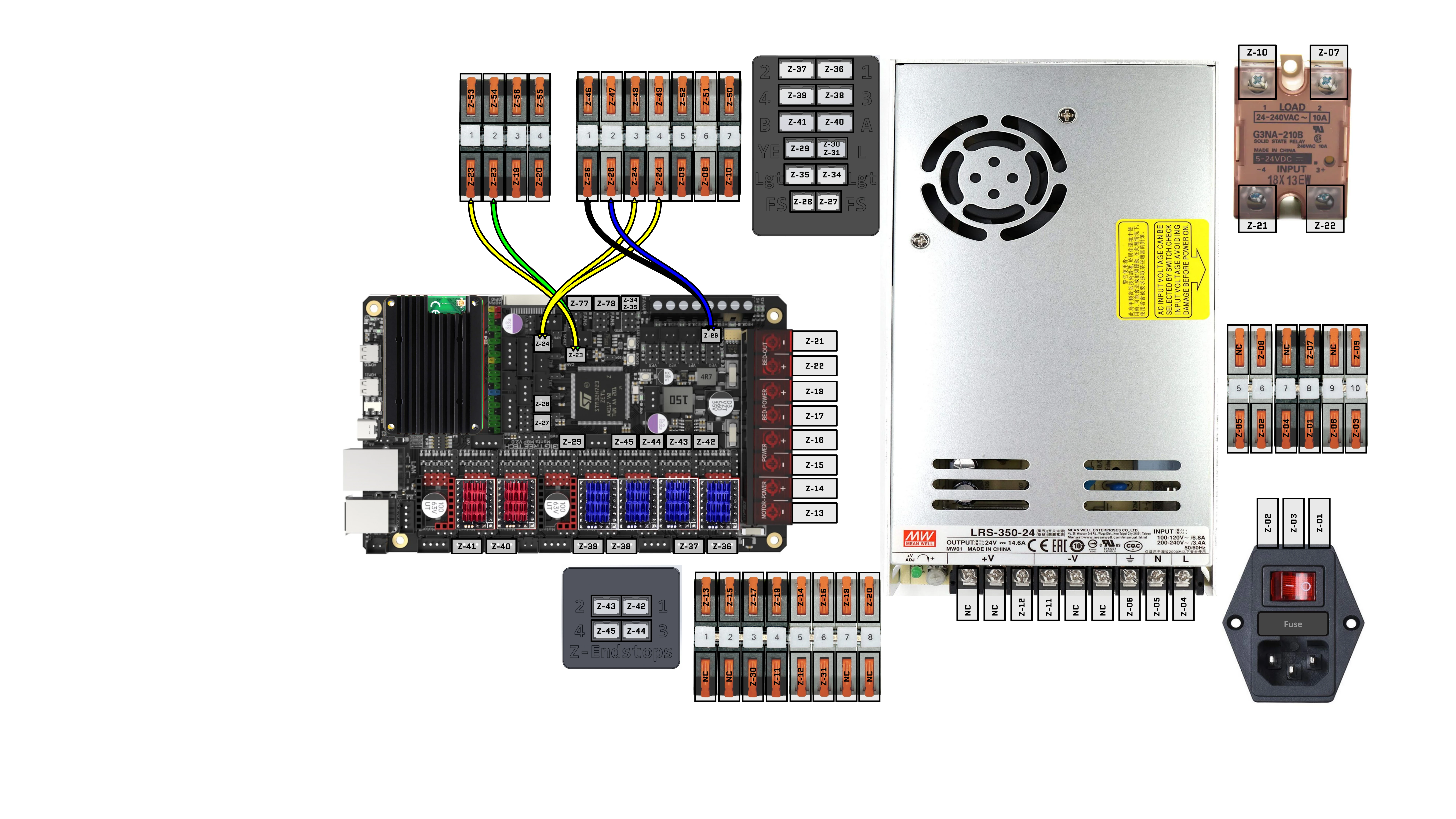
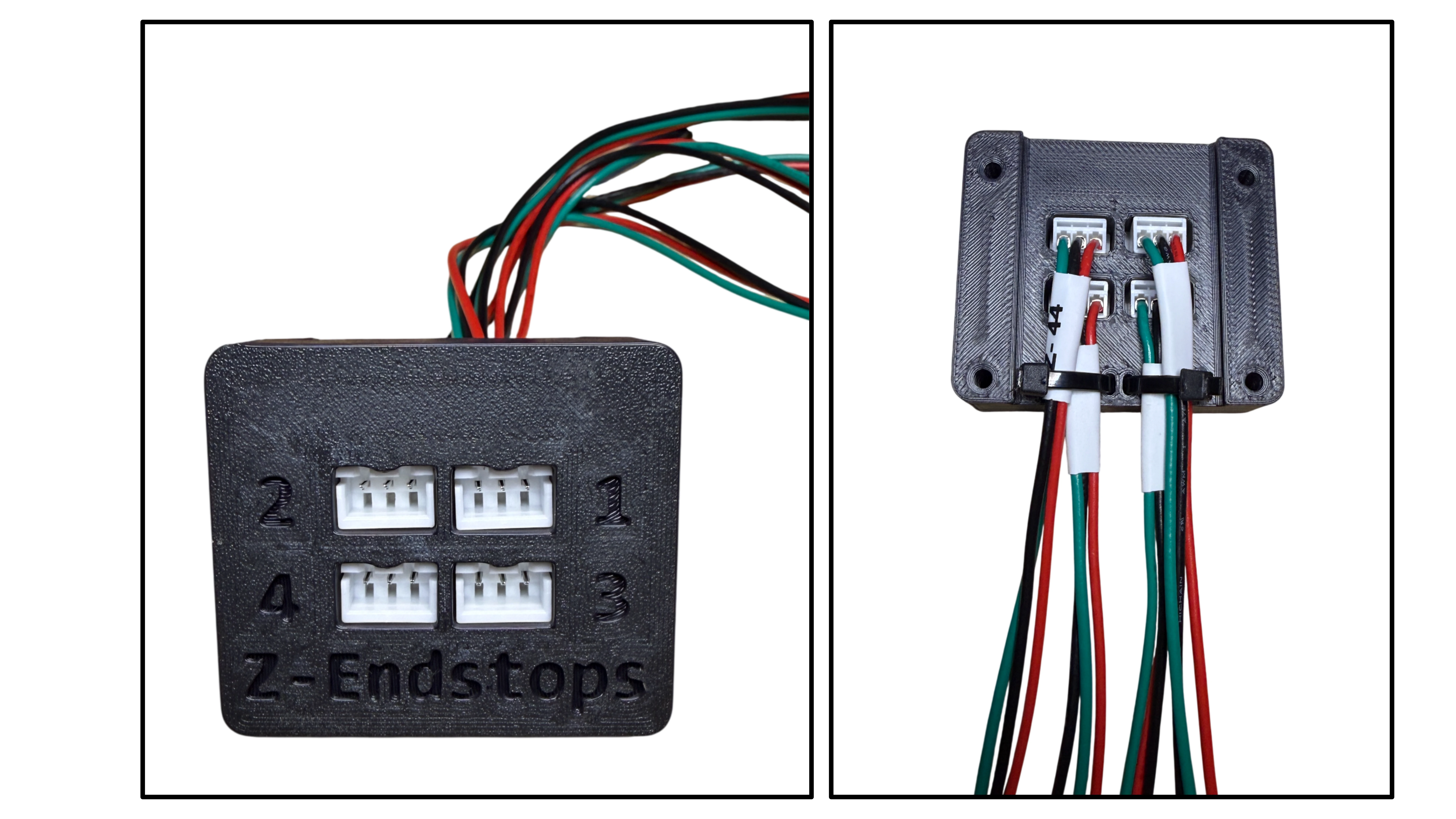
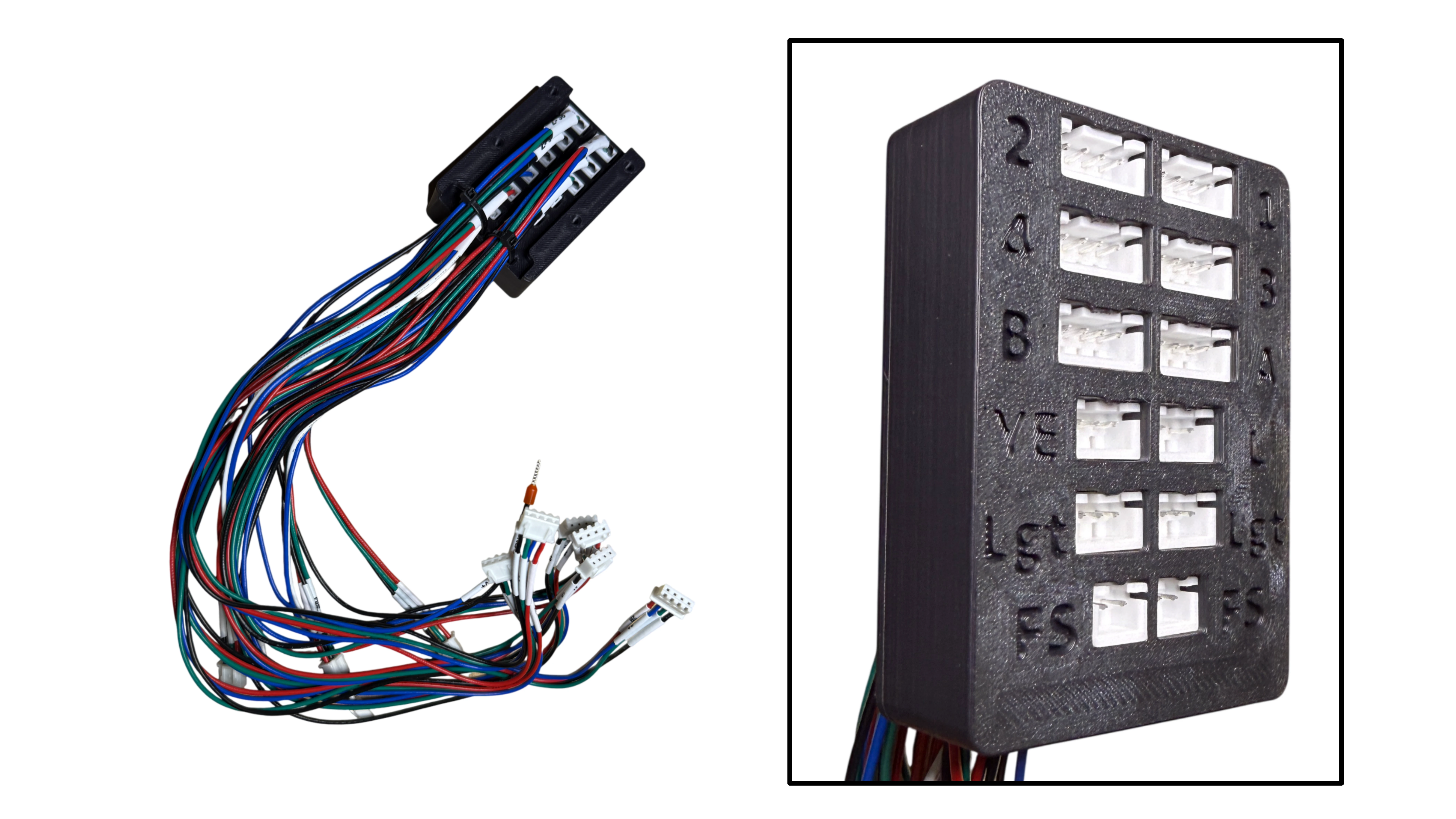
27. Assembling Peripheral Blocks
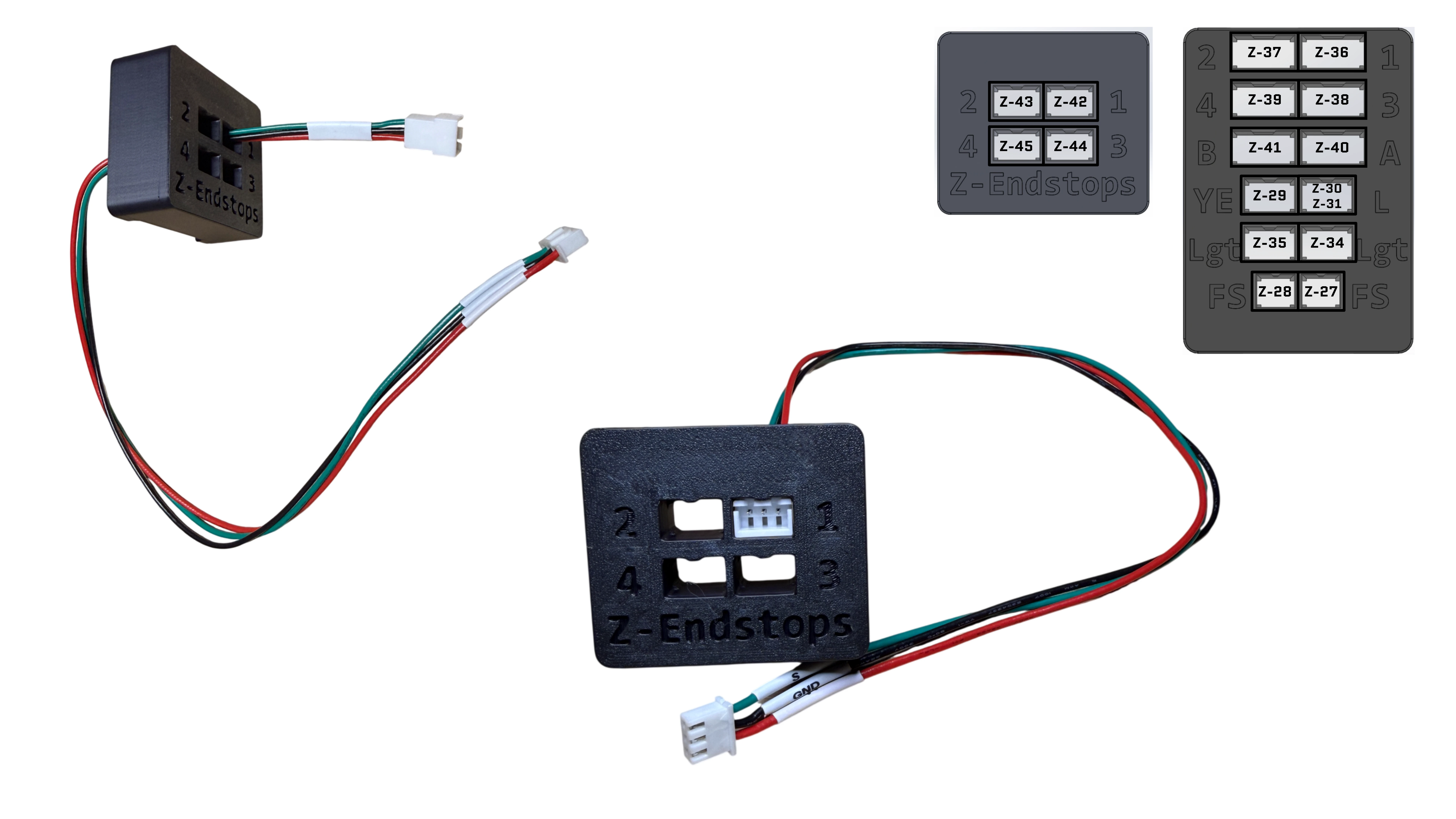
- Feed cables through peripheral block
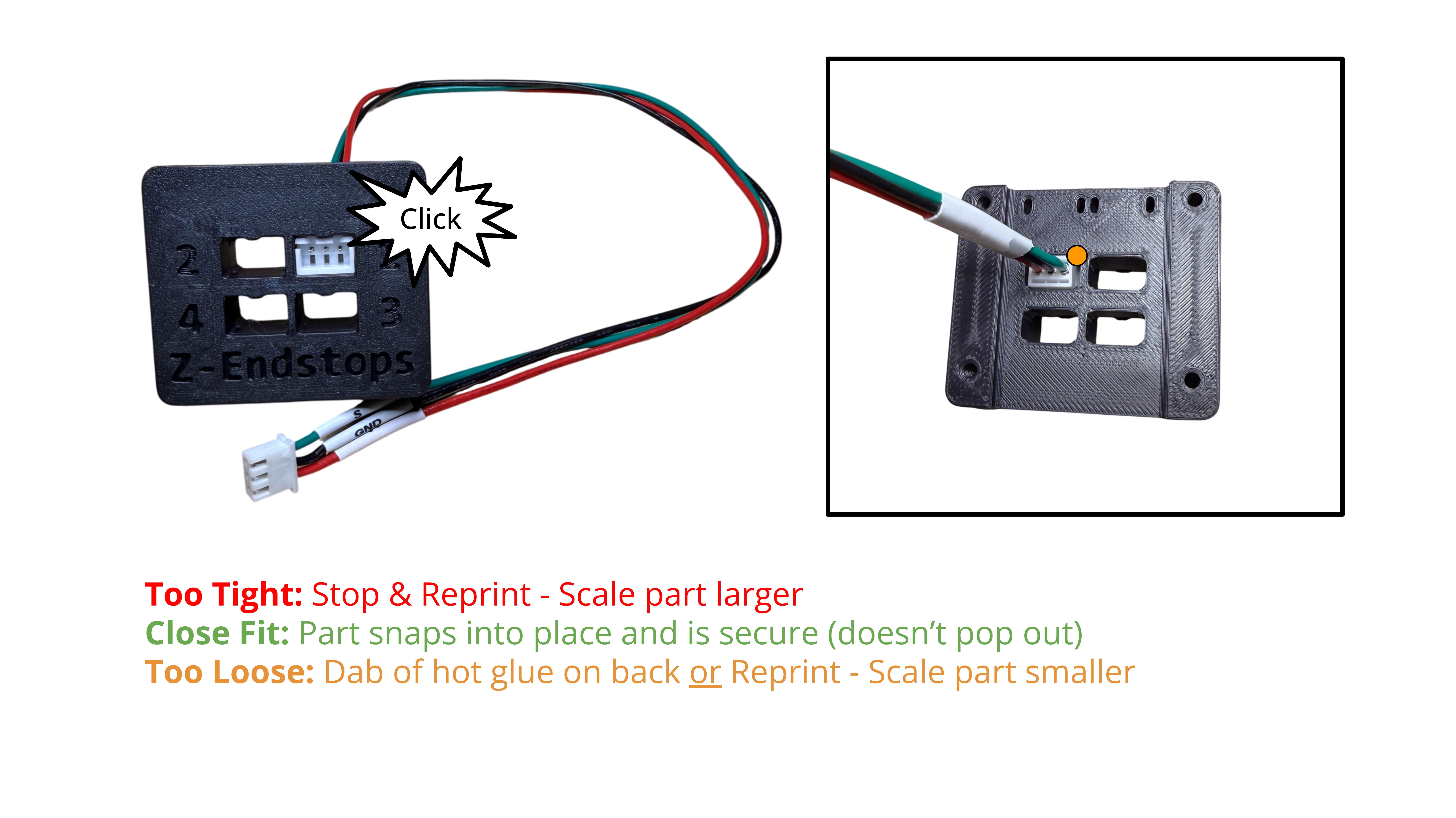
- Connector should be held snug by peripheral block when pushed into place.
- Evauluate the fit
- Too Tight: stop and reprint - scale part larger
- Good Fit: Part snaps into place and is secure (doesn’t pop out)
- Too Loose: Dab of hot glue on back or Reprint - Scale part smaller
- Evauluate the fit
- Optional: Apply labels or indicators at connector.
- Apply zip-ties
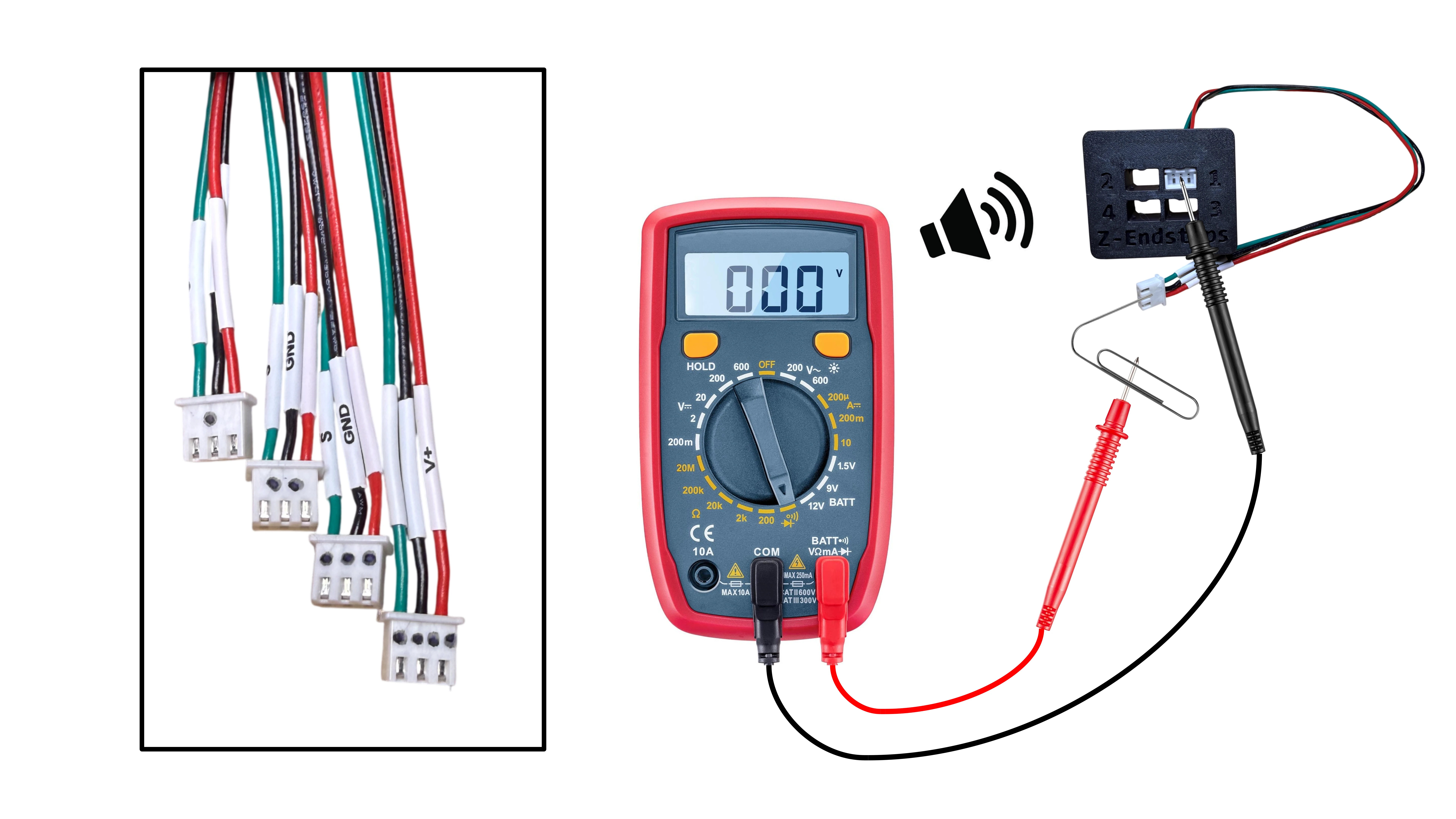
Before zip typing cables in next steps, you can add indicators or simply the Z-codes on the connector with sharpie. Otherwise, the cables can be identified using a continuity test as they are connected to the main board in later steps - Hold off plugging them in for now! A paperclip provides good access for the female connectors.
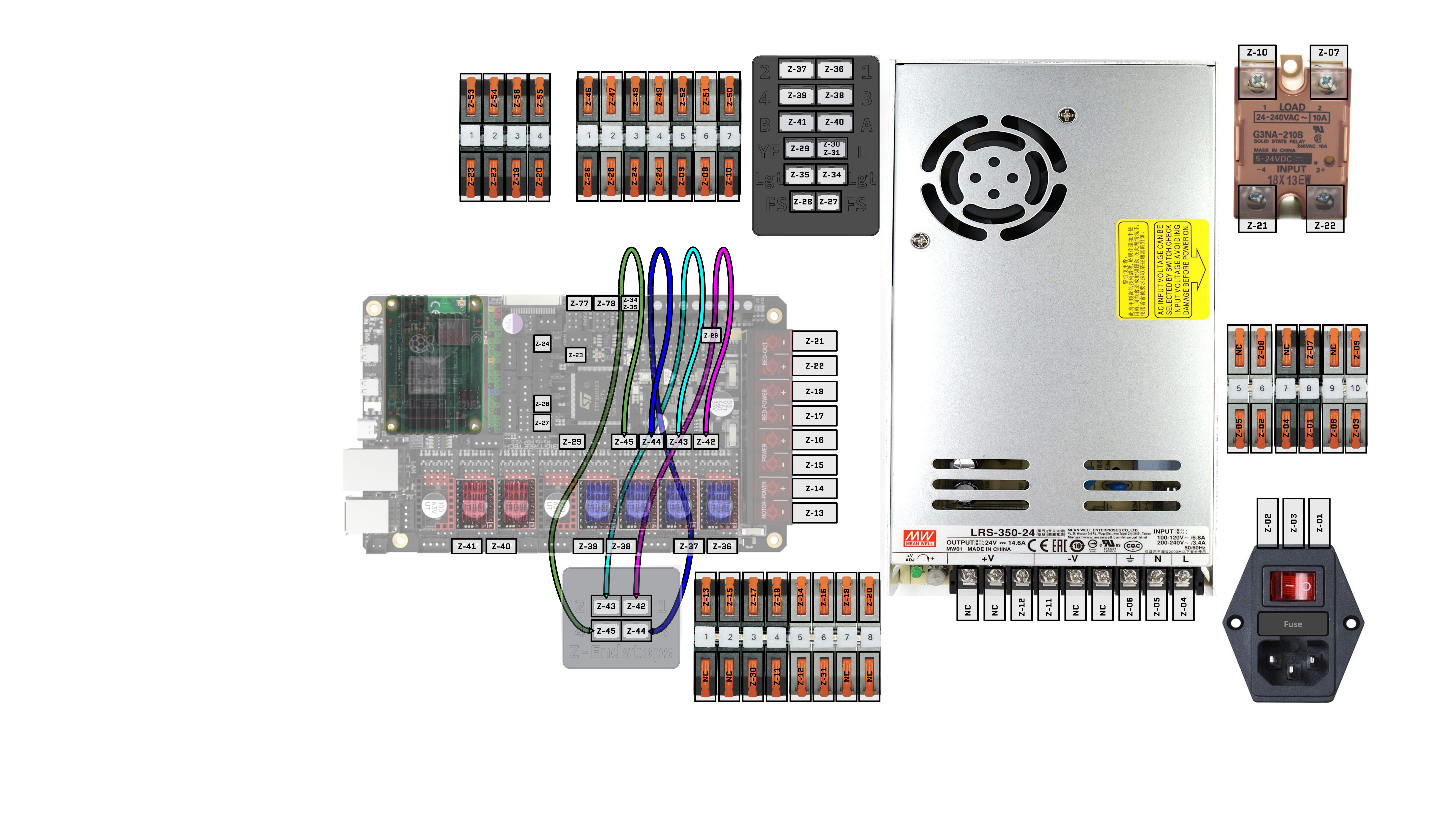
28. Install Cables: Z-42, Z-43, Z-44, Z-45
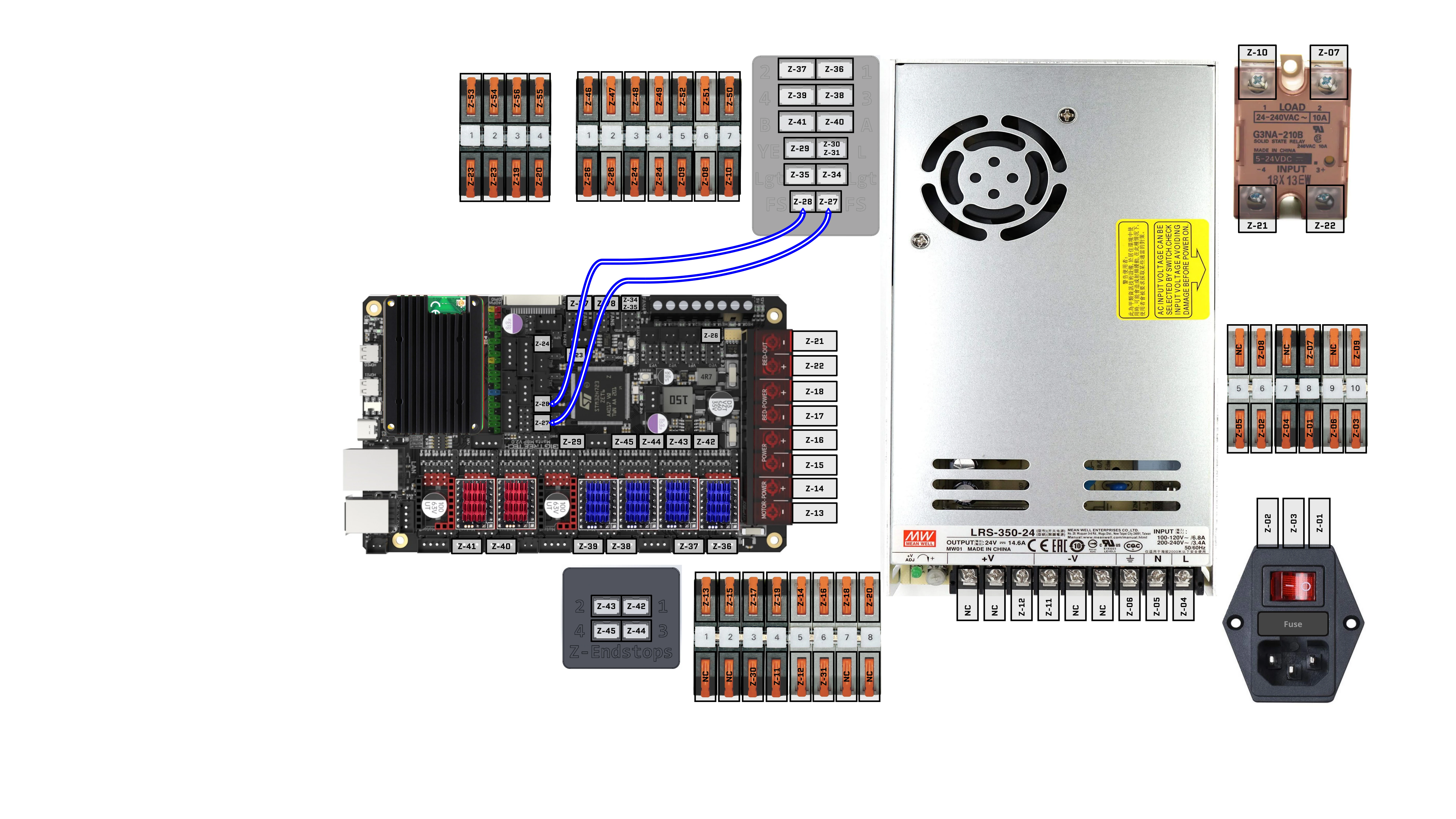
29. Install Cables: Z-27, Z-28
30. Install Cables: Z-34, Z-35, Z-32/33
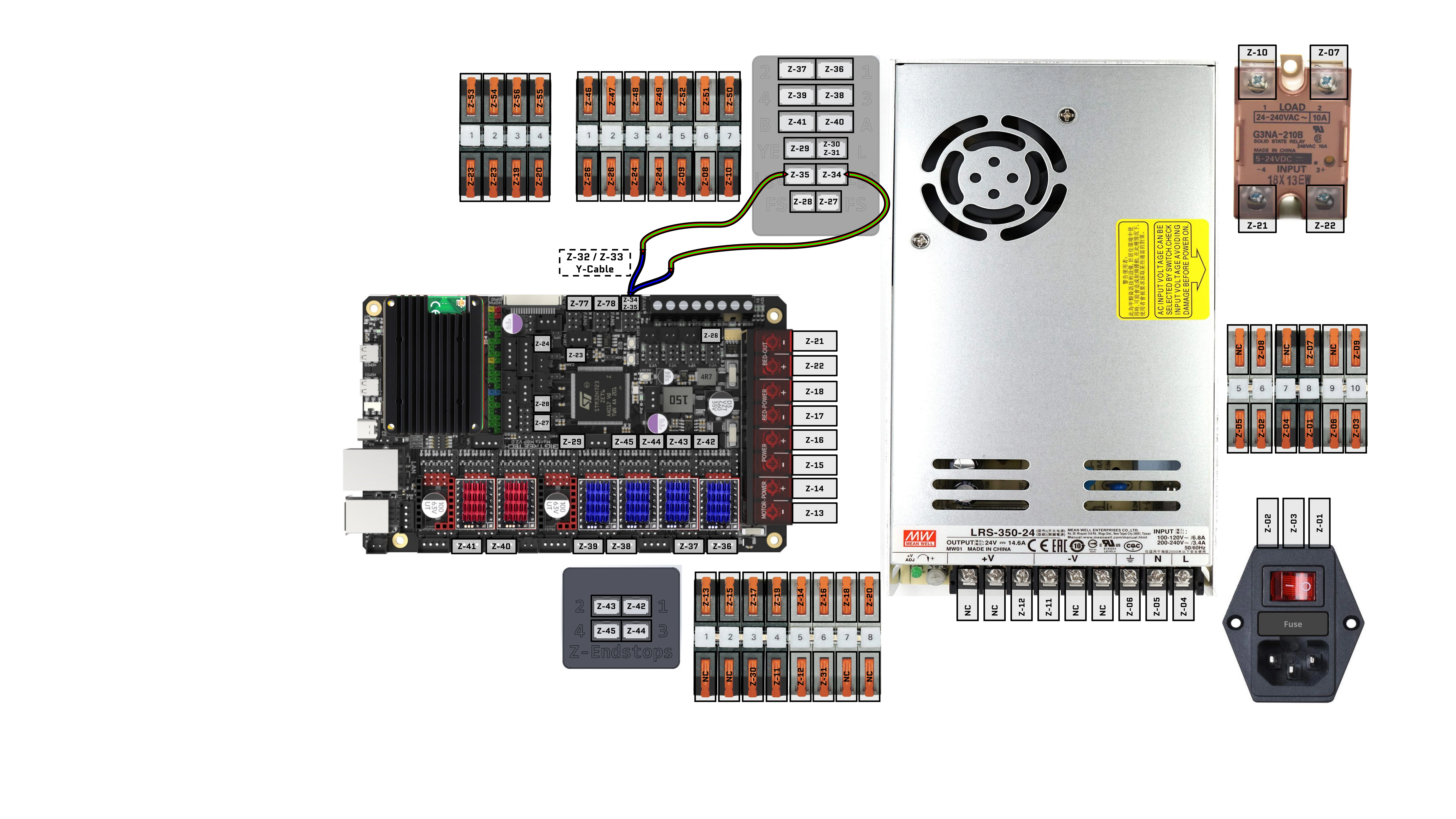
31. Install Cables: Z-29, Z-30, Z-31
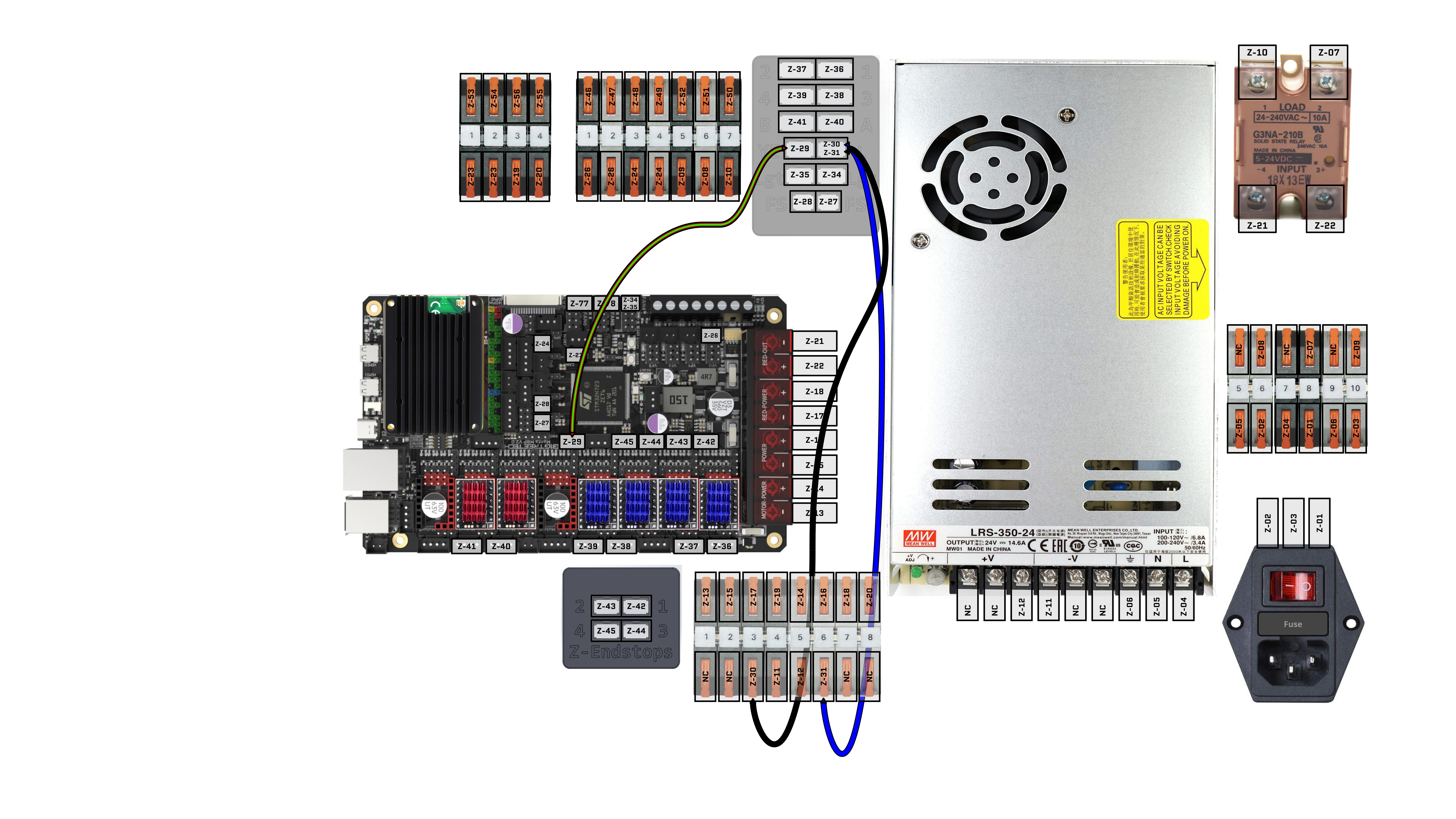
32. Install Cables: Z-40, Z-41
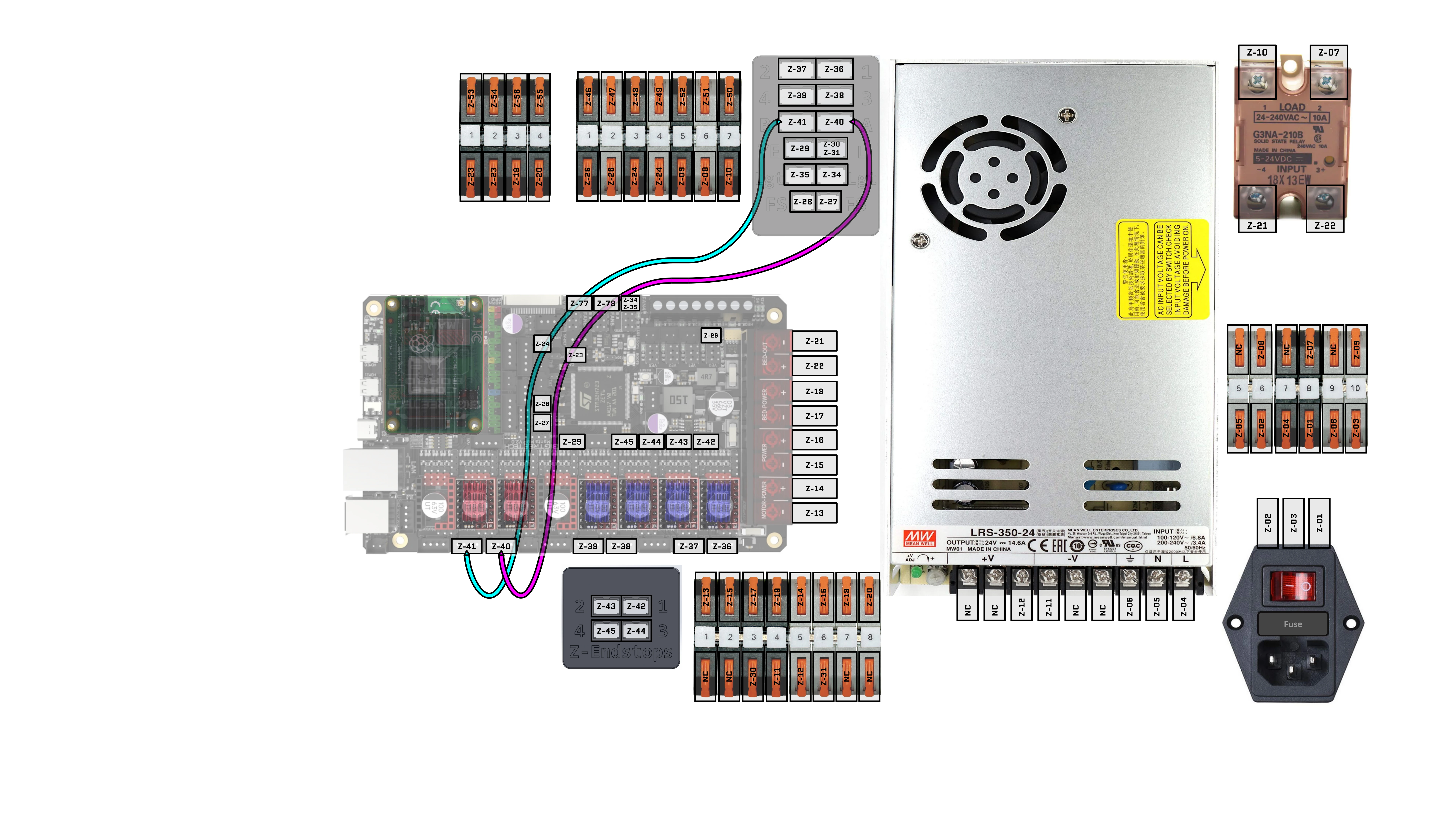
33. Install Cables: Z-38, Z-39
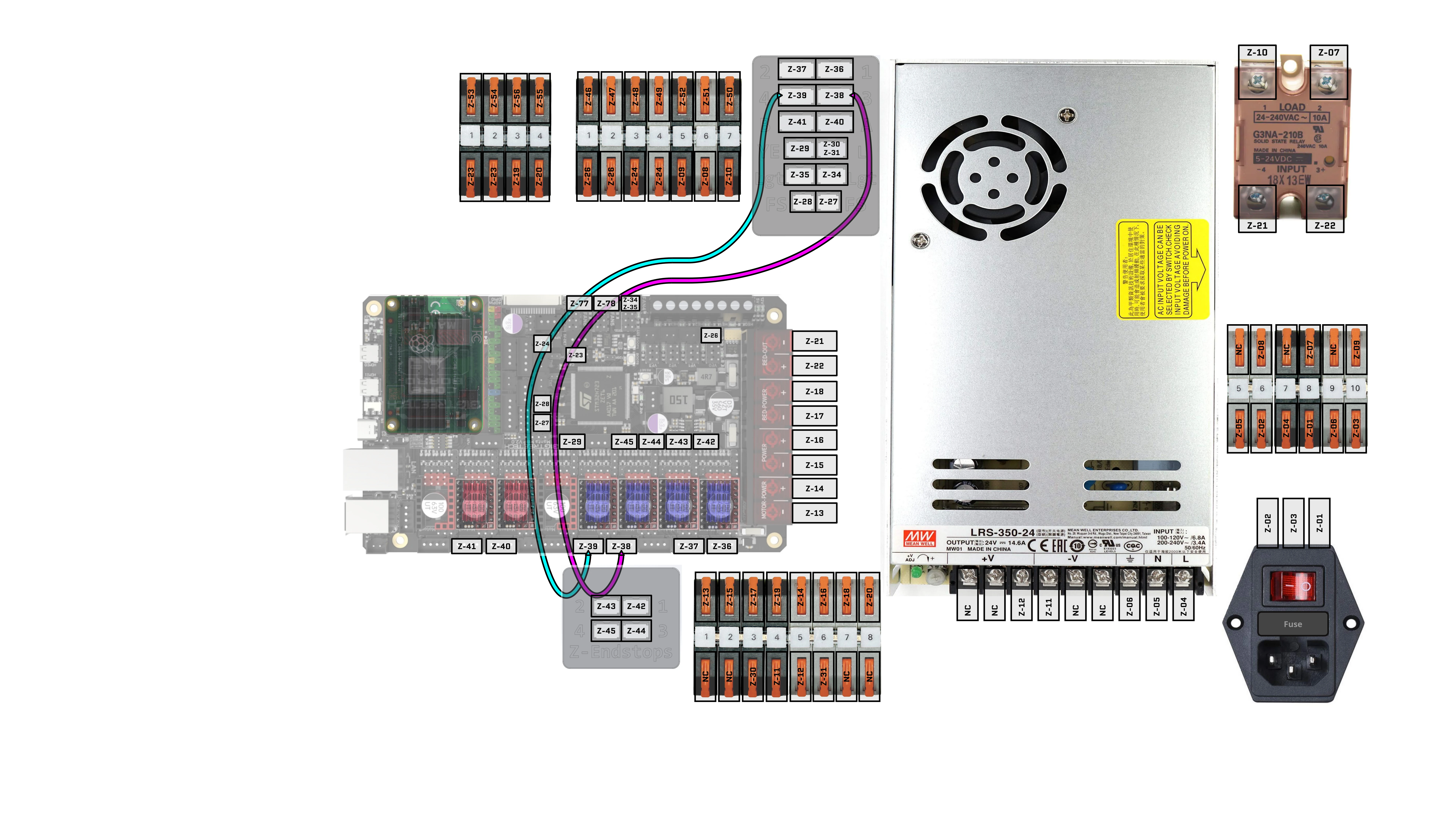
34. Install Cables: Z-36, Z-37
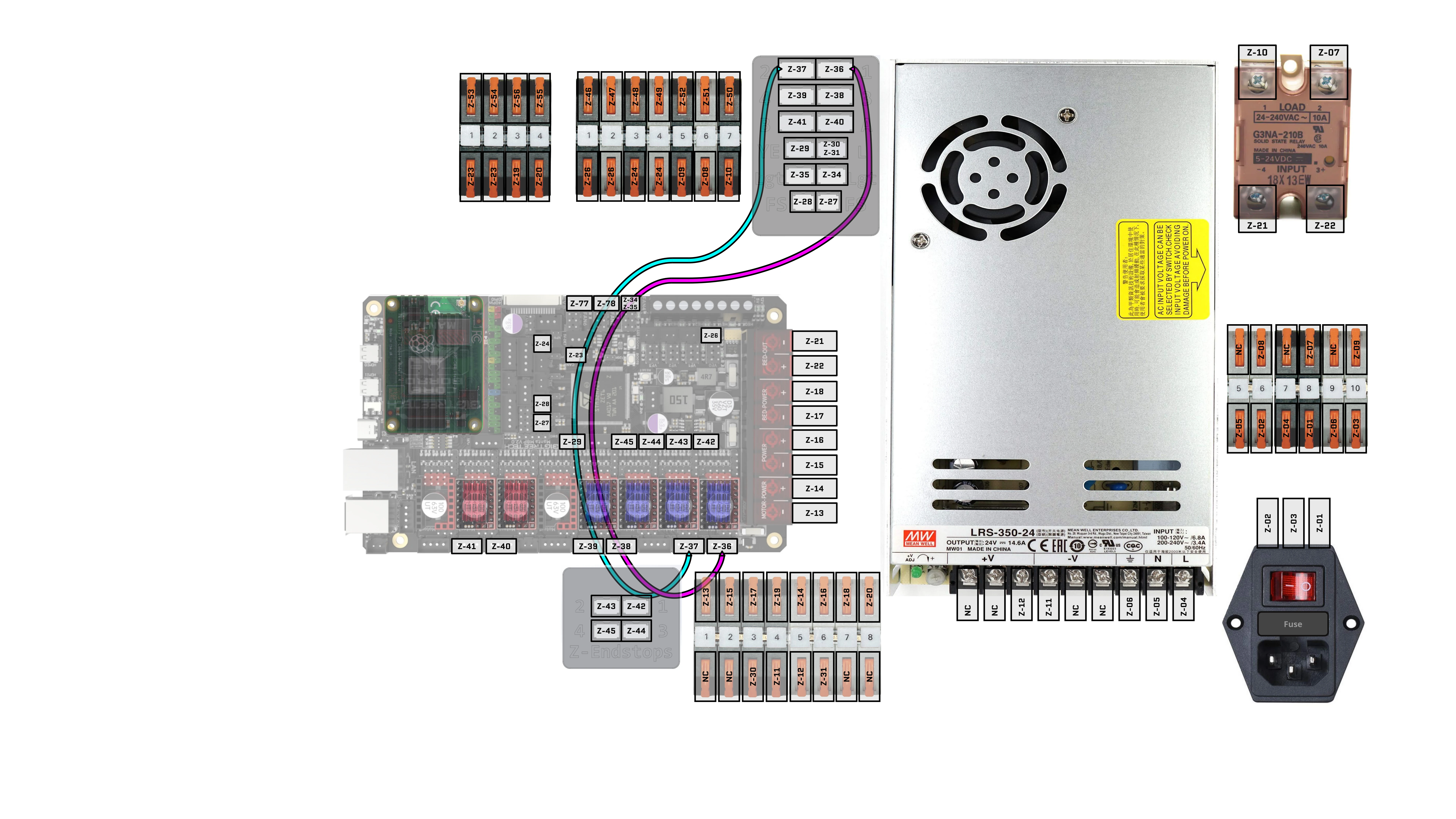
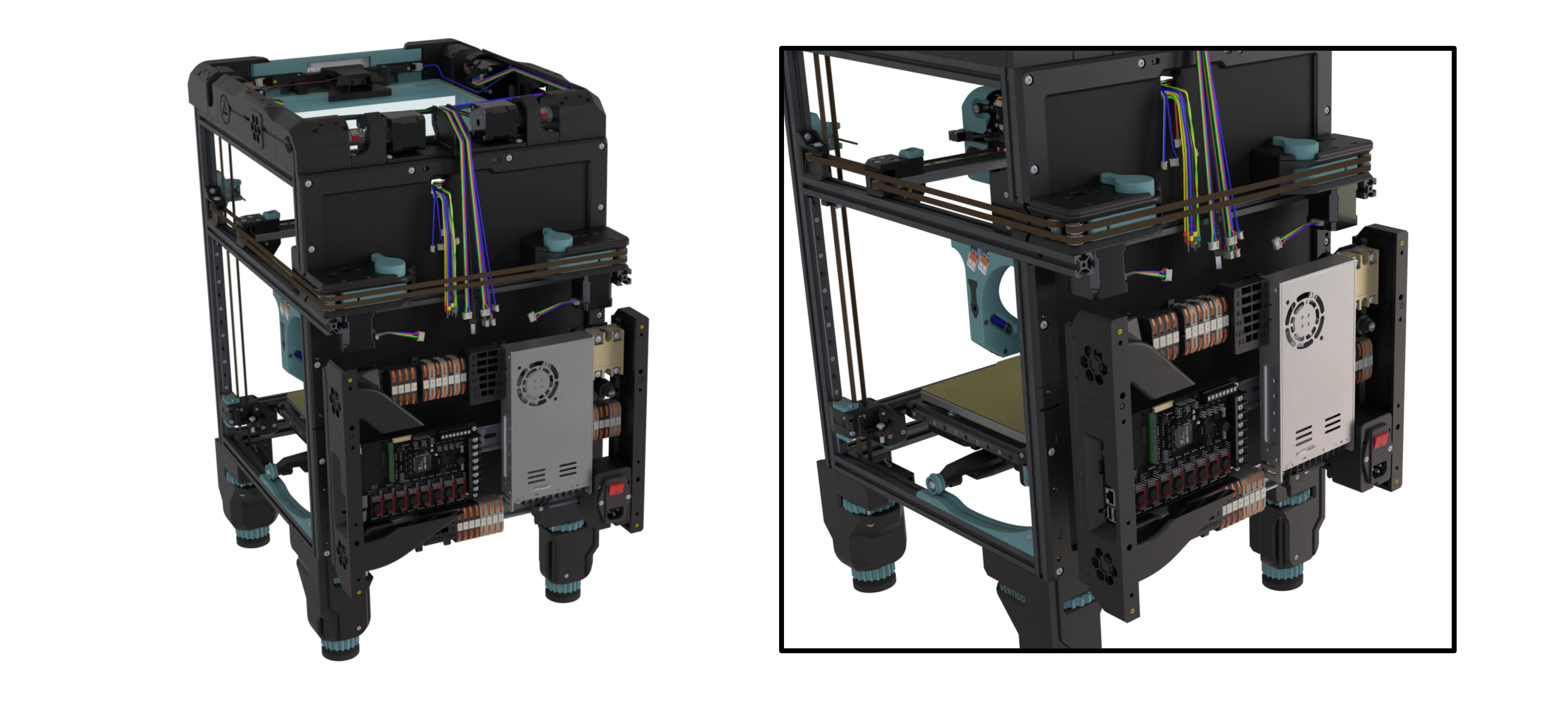
35. Complete the Electronics Backpack Section then Continue
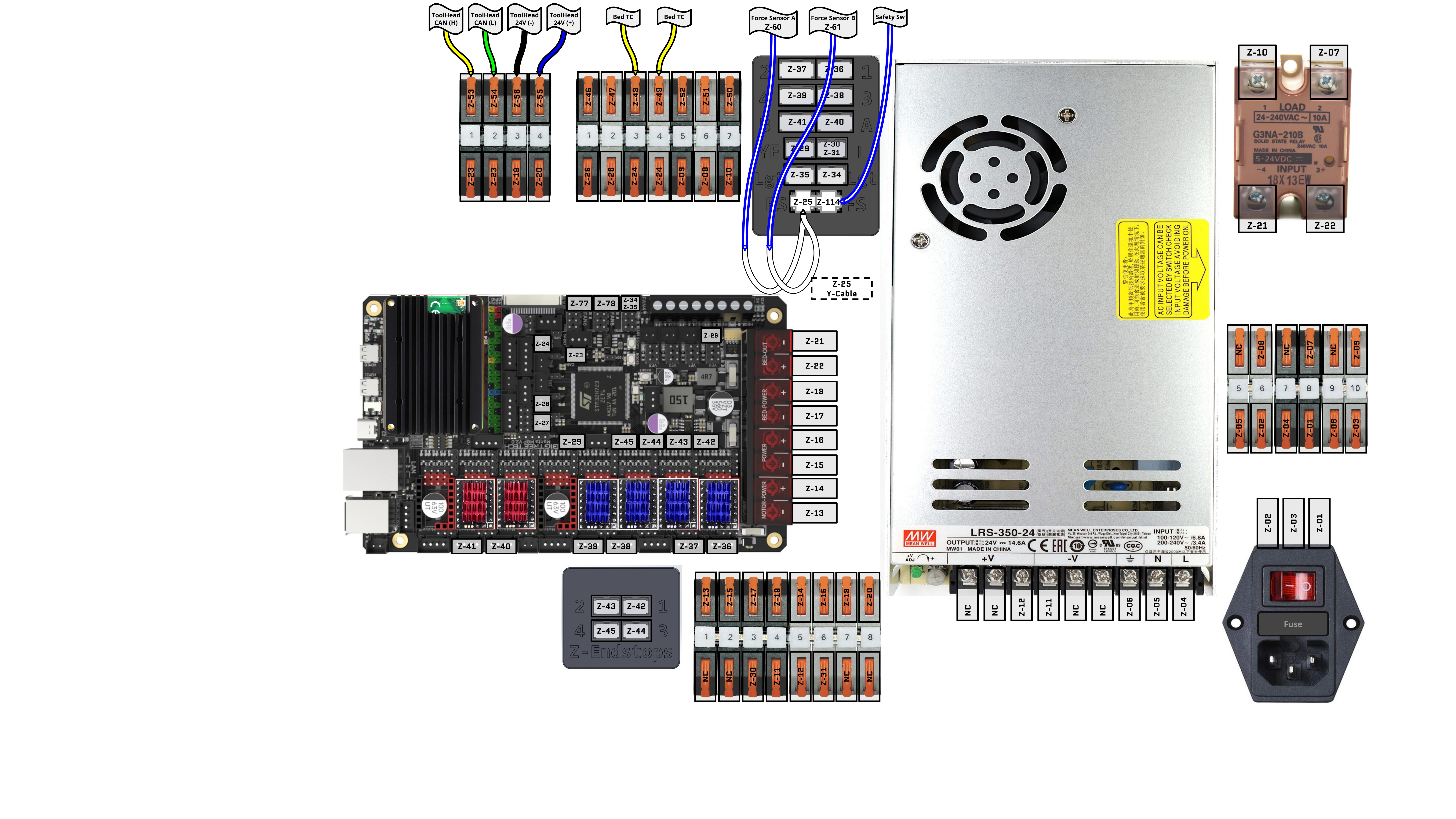
36. Install Cables: Z-25, Z-48, Z-49, Z-53, Z-54, Z-55, Z-56, Z-60, Z-61, Z-114
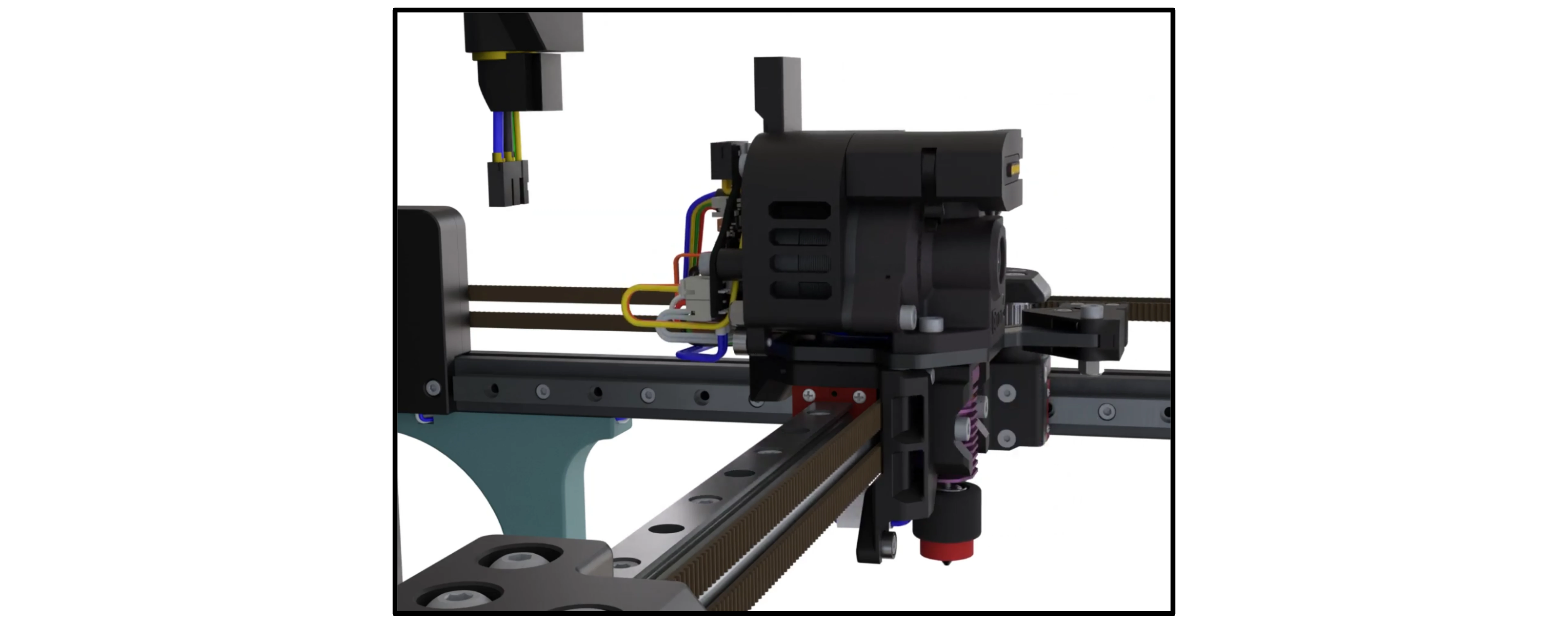
37. Unplug Toolhead’s XT30 Connector
38. Checking Toolhead Power
- Safety First: Ensure you and others around you observing are wearing the appropriate PPE. Also have your safety equipment on hand
- Ensure the toolhead is unplugged
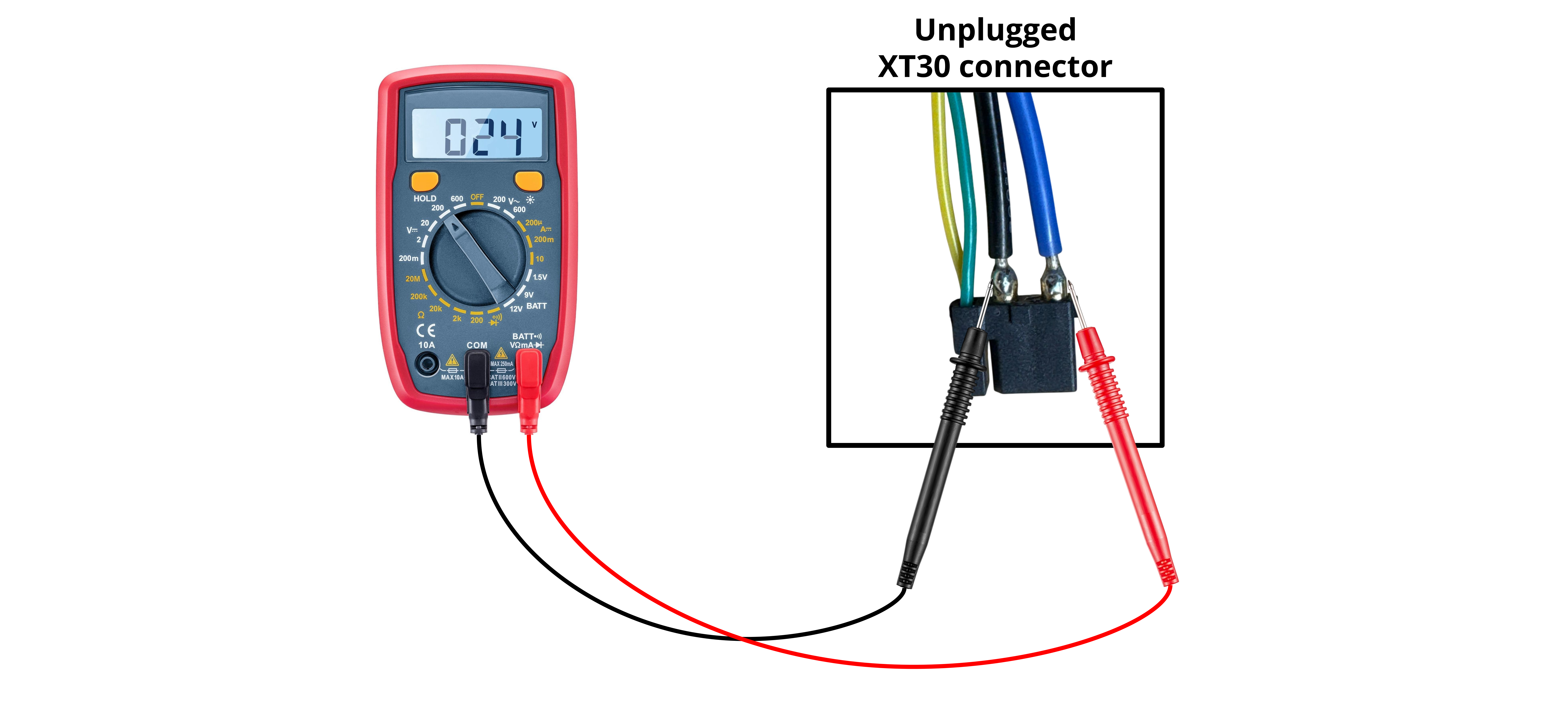
- Set voltmeter to DC Voltage Mode, choosing the lowest limit that is >=24V. In our image, that number is 200
- Power ON the printer
- Touch the voltmeter’s leads to the XT30 connector as shown - Approach from the outside as to not cause an accidental short
- Black to Black
- Red to Blue
- The voltmeter should read a positive 24V
- Power OFF the printer
Pass: Voltmeter reads positive +24V
Fail: Voltmeter reads negative -24V, or any other value
Polarity matters! Make sure you are touching the correct leads to the correct points. This is the last safety check to save your toolhead board.
39. PZ Probe Controller Cable: Z-105, Z-106, Z-107
- This cable needs a little extra explanation.
- Z-105 and Z-106 are used to program trigger variables outside of E3D’s preset options. These connectors are not required for normal operation and can either be tucked behind the toolhead board for later use or removed.
- Z-107 provides power to the PZ Probe Controller and carries the trigger signal.
- Verify Z-107 pinout on both ends of the connector and make sure power, ground, and signal are routed correctly
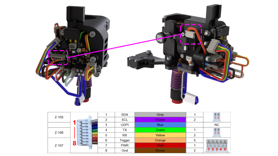
The PZ Probe Controller is fragile and can be damaged if Z-107 is wired incorrectly.
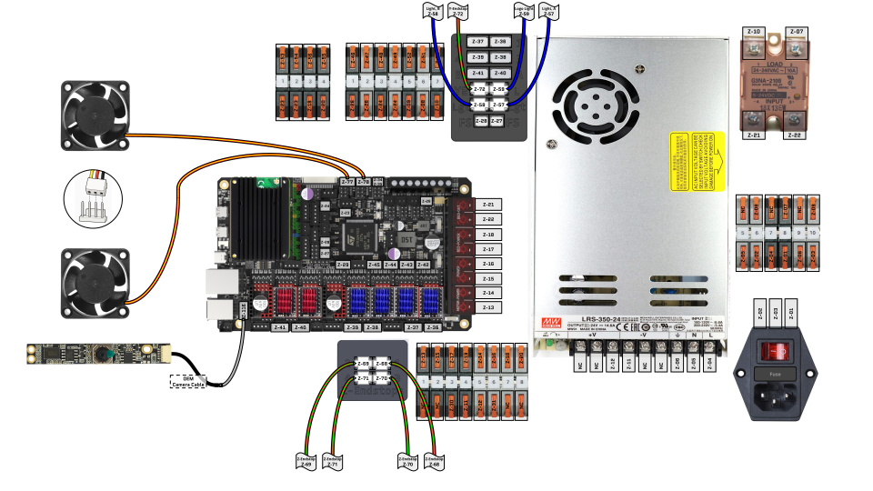
40. Install Lights, Endstops, Electronics Fans, Camera: Z-57, Z-58, Z-59, Z-68, Z-69, Z-70, Z-71, Z-72, Z-77, Z-78, Z-116
41. Endstop Check
- This step checks the Z-endstop wiring at the board connection to confirm the wiring is correct.
- Unplug and test one endstop at a time so each connector can be easily returned to its original location after testing.
- Paperclips can be used to make it easier to access the female pins during the check.
Preprequisite:
- Power is disconnected
- Set multimeter to continuity mode
- Multimeter continuity mode tested and working (beeps when touching leads)
Test:
- Unplug endstop cable from the board connection.
- If needed, insert paperclips into the V+ and Signal lines of the endstop cable as shown.
- Touch multimeter leads to paperclips.
- Plug endstop cable back into the board.
Pass: Multimeter beeps when the switch is not pressed; no sound when the switch is pressed.
Fail: Any other behavior
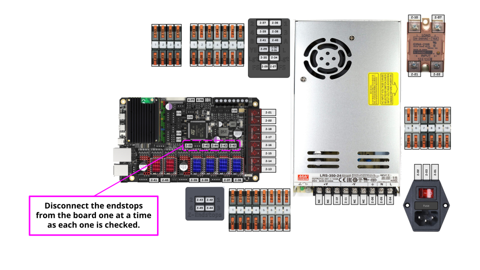
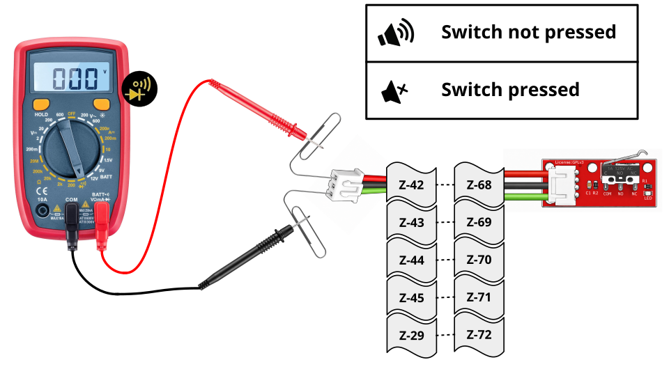
Incorrect endstop wiring could short power to ground, so this check is important!
42. Electronics Fans Pinout Check: Z-77, Z-78
- Check that the electronic fan pinout is wired as shown.
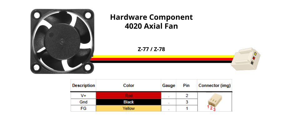
The electronic fan pinout on the first batch of kits was commonly reported NOK, so please check it before proceeding.
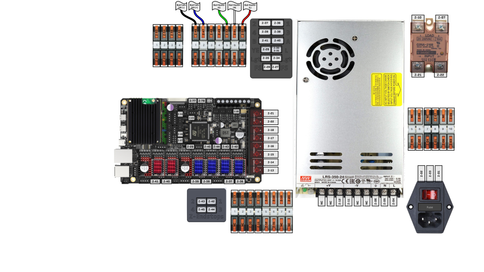
43. Install Bed Heater, Bed Fans: Z-46, Z-47, Z-50, Z-51, Z-52
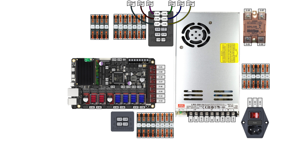
44. Install Stepper Motors: Z-46, Z-47, Z-50, Z-51, Z-52
Continue to the Firmware Guide
This concludes the electronics backpack wiring required for firmware installation. We will integrate the remaining components in later steps.
At this stage, only the cables that we have covered should be connected.